Self-propelled vehicle for use in a conduit

a self-propelled vehicle and conduit technology, applied in the direction of magnetic measurement, cleaning of hollow articles, railway tracks, etc., can solve the problems of unsuitable for providing strong frictional engagement with pipes, designing vehicles capable of travelling through and operating in enclosed spaces such as pipes, channels, ducts or other conduits, and reducing maintenance costs. , the effect of reducing maintenance costs

Inactive Publication Date: 2009-10-06
CR PIPELINE SERVICES
View PDF28 Cites 22 Cited by
  • Summary
  • Abstract
  • Description
  • Claims
  • Application Information

AI Technical Summary

Benefits of technology

[0016]The legs are preferably of equal length, angularly spaced equidistantly around each member and mounted to allow each actuator to accurately centre each member and consequently centre the vehicle within a tubular conduit. Preferably the legs are pivotally mounted to the member.
[0018]A foot on which the wall-engaging surface is provided is preferably connected to or formed on each of the legs. The feet serve to spread the contact area, avoiding high point loads which may damage the pipe walls. In one embodiment each foot may be pivotally mounted to the leg. According to the conditions anticipated to be encountered in the conduit, the type of feet utilised may also be rigid or may be provided with a contact surface of resilient material for high friction.
[0021]The wall-engaging mechanism mounting the feet on the rearward member preferably includes a self-servo action automatically increasing the frictional engagement between the feet and the conduit when a rearwardly directed force is applied to the rearward member when the feet are engaged.
[0026]The robust and adaptable nature of the wall-engaging mechanism permits high frictional forces to be applied via the feet. Thus, positive movement of the vehicle may be maintained to overcome obstruction, or to aid carrying / pulling heavy loads.
[0042]This invention provides a vehicle for use in conduits which is effective and efficient in operational use, which reduces maintenance costs, and which is modular in construction allowing it to be used with different means for removing material from the conduit. It will be understood that a camera and light may be mounted to the vehicle for inspection purposes. The device may be economically constructed and has an overall simple design which minimizes manufacturing costs and maximizes performance.

Problems solved by technology

Remote-controlled vehicles can be used for carrying tools, or other items, and can travel into hazardous or confined areas where human workers cannot go.
However, designing vehicles capable of travelling through, and operating in, enclosed spaces such as within pipes, channels, ducts or other conduits, has presented difficulties.
A disadvantage with such vehicles is that they are unsuited to provide strong frictional engagement with the pipe, such as may be required when performing different operations within the pipe, such as clearing an obstruction.
A mechanical breakdown of the vehicle within a pipe can result in considerable cost and inconvenience and thus mechanical complexity, with the attendant risk of a malfunction, is disadvantageous where it does not provide significantly improved performance.
This prior art vehicle is designed for use in oil pipelines and is of relatively complex construction making it potentially expensive and difficult to operate and maintain.
In particular, the complexity of this vehicle is increased by the provision of separate hydraulic actuators for extending each of the nine legs.
Independent actuation of each leg in the vehicle is also disadvantageous where it is desired to accurately centre the vehicle within the pipe.

Method used


Image

  • Self-propelled vehicle for use in a conduit
  • Self-propelled vehicle for use in a conduit
  • Self-propelled vehicle for use in a conduit

Examples


first embodiment

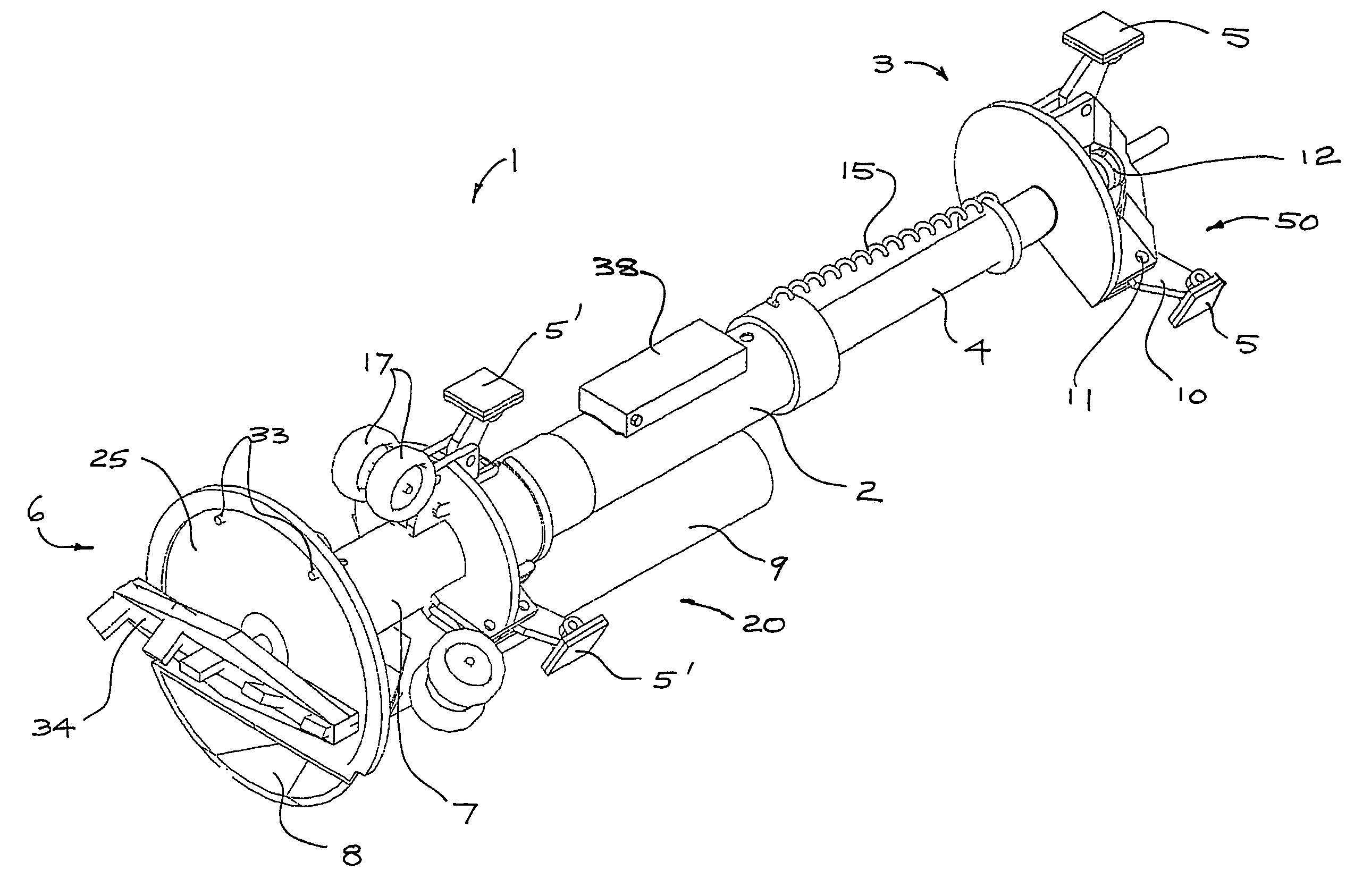
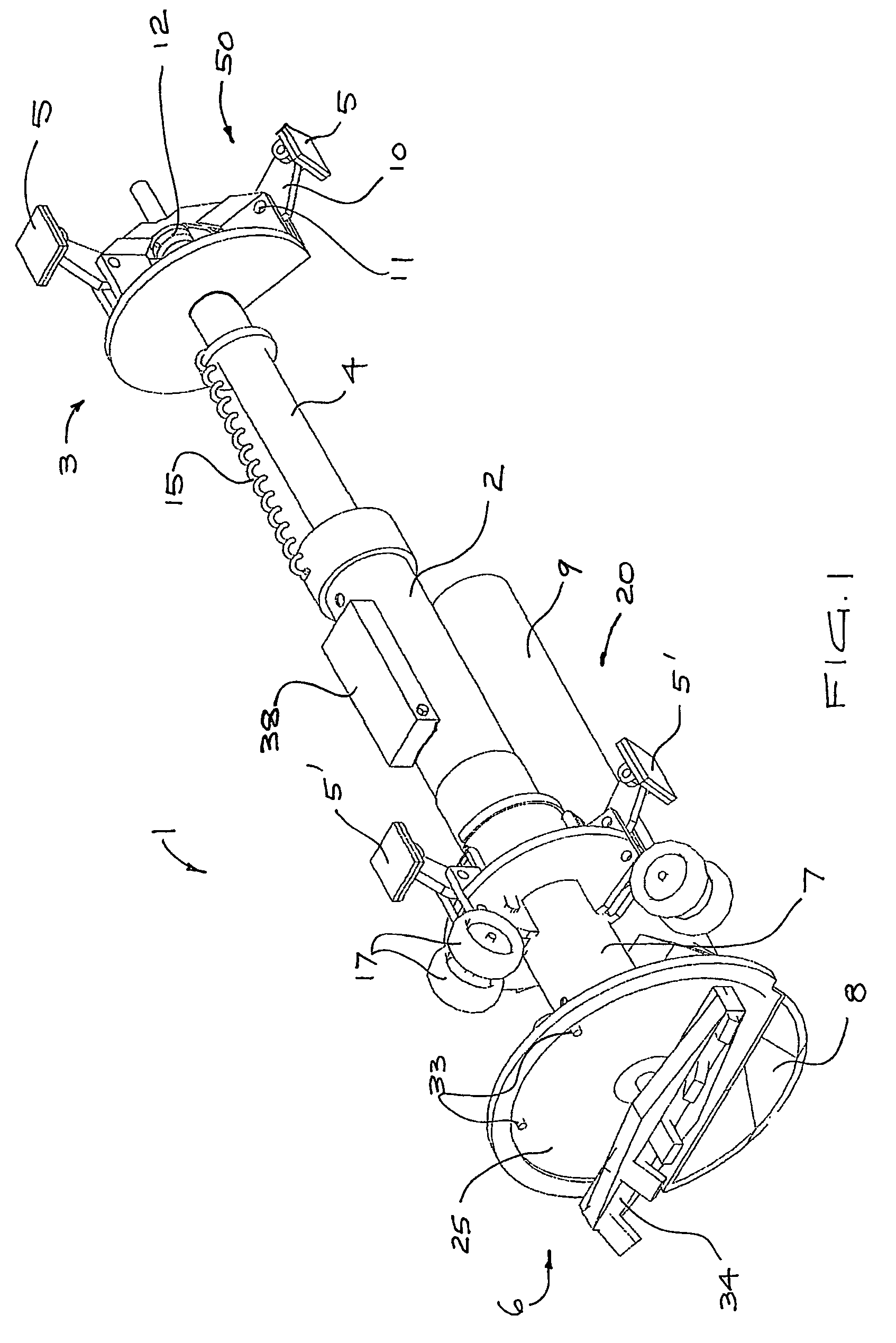
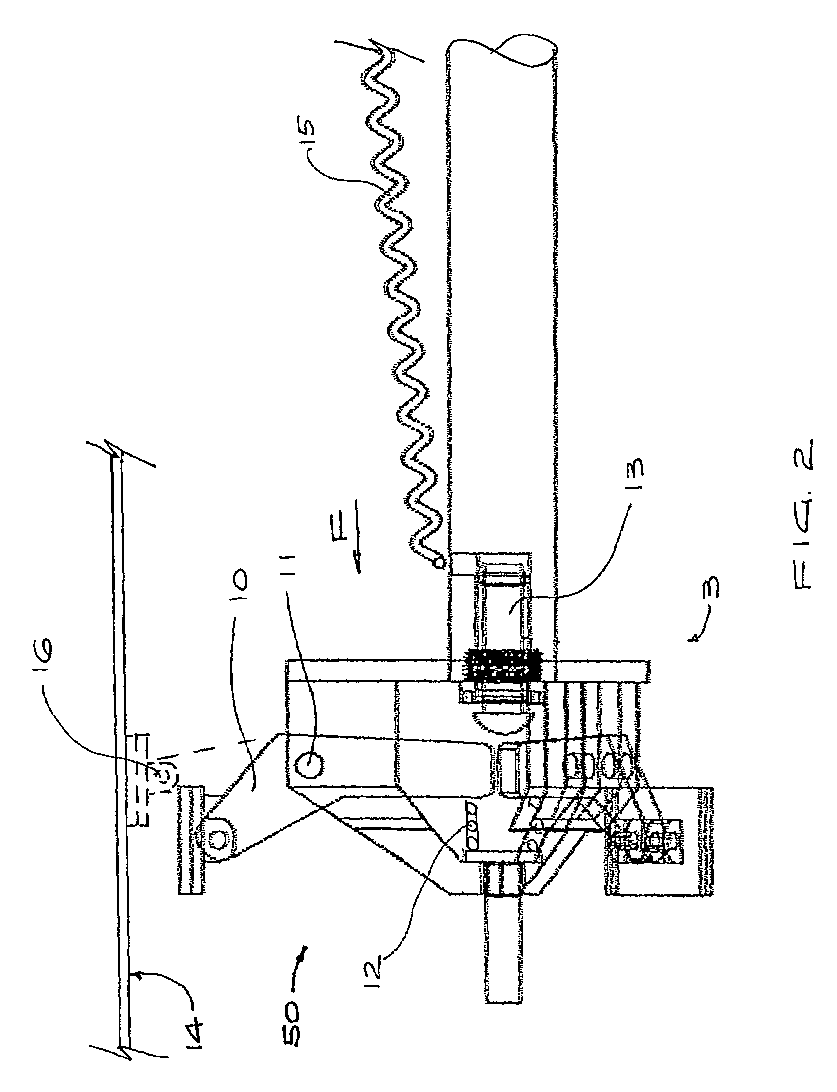
[0053]FIG. 1 illustrates the vehicle of the present invention fitted with conduit cleaning apparatus. The vehicle generally comprises a forward member 1 mounted to a hydraulic cylinder 2, and a rearward member 3 mounted to a rod 4 received in the cylinder 2. A power actuated wall-engaging mechanism (described further with reference to FIGS. 2, 3a and 3b) is provided on both the forward and rearward members 1 and 3 for extending and retracting feet 5′ and 5 respectively for selectively engaging the inner wall of a conduit 14 (see FIG. 2) to hold the members stationary. By coordinating the engagement and disengagement of the feet 5, 5′ with the movement of the forward and rearward members 1, 3 by the hydraulic cylinder 2 and rod 4, the apparatus may propel itself through the conduit 14 in either direction in a stepwise manner.

[0054]A rotary cutter 6 mounted at the front of the forward member 1 on a hydraulic motor 7 is provided for loosening material to clear or clean the conduit 14. ...

second embodiment

[0063]the vehicle is illustrated in FIGS. 4-8 and like numerals are used to refer to like components. The wall-engaging mechanism 50a on the rearward member 3 is also arranged generally symmetrically about the central elongate axis A of the vehicle, the feet being angularly spaced at 120°. The mechanism 50a extends and retracts the feet 5a generally radially and includes control links 66 for maintaining the wall-engaging face of each foot 5a generally parallel to the wall of the pipe. The wall-engaging mechanism 50a includes three rear legs 10a angularly spaced, each of the legs 10a being fixed between a pair of control links 66 connecting each foot 5a to the rearward member 3.

[0064]Each leg 10a is pivotally attached to the foot 5a at an outer end by a first pivot 61 and to a mount 62 fixed to the rearward member 3 by a second pivot 63. A roller 64 fixed to an inner end of the leg 10a and the three rollers 64 are received between two radially-extending flanges 69a, 69b fixed to the ...


PUM

PropertyMeasurementUnit
lengthaaaaaaaaaa
distanceaaaaaaaaaa
radiusaaaaaaaaaa

Abstract

A vehicle for travel through a conduit includes a forward and a rearward member, each member being provided with a wall-engaging mechanism for selectively engaging a wall of the conduit to hold the respective member in a stationary position within the conduit. Extensible elements such as a hydraulic ram connect the members for relative movement of the forward member toward and away from the rearward member. Each wall-engaging mechanism includes a plurality of legs extendable outwardly from the respective member and a wall-engaging surface on or fixed to each leg, one actuator engages each of the legs for coordinated extension of the legs to bring each wall-engaging surface into contact with the wall of the conduit. Preferably a rotary cuter is mounted at the front of the vehicle for clearing obstructions in the conduit.

Description

TECHNICAL FIELD[0001]The invention relates generally to self-propelled vehicles for use in conduits, and in particular to remote-controlled vehicles with apparatus for cleaning conduits.BACKGROUND ART[0002]Remote-controlled vehicles can be used for carrying tools, or other items, and can travel into hazardous or confined areas where human workers cannot go. However, designing vehicles capable of travelling through, and operating in, enclosed spaces such as within pipes, channels, ducts or other conduits, has presented difficulties.[0003]One class of such vehicles are those which are self-propelled by a linear actuator, or the like. These vehicles include two bodies connected by the actuator for moving the bodies towards and away from each other, by which movement the vehicle is able to propel itself through the pipe in a stepwise manner. The bodies may include bristles or bladders for engagement with the wall of the pipe. A disadvantage with such vehicles is that they are unsuited t...

Claims


Application Information

Patent Timeline
Patent Type & Authority Patents(United States)
IPC IPC(8): B61B13/10G01N27/82B08B9/02B08B9/04B08B9/049F16L55/00F16L55/26F16L55/34
CPCB08B9/035F16L55/34B08B9/051B08B9/049
Inventor NICHOLSON, COLIN BRUCE
Owner CR PIPELINE SERVICES
Why Eureka
Try Eureka