Method for making a smart card antenna on a thermoplastic support and resulting smartcard

a technology of thermoplastic support and smart card, which is applied in the direction of casing/cabinet/drawer details, instruments, casings/cabinets/drawers, etc., can solve the problems of difficult manufacturing of electronic modules and antennas, inability to maintain the shape factor of antennas, and increased manufacturing costs

Inactive Publication Date: 2009-10-06
ASK SA (FR)
View PDF18 Cites 32 Cited by
  • Summary
  • Abstract
  • Description
  • Claims
  • Application Information

AI Technical Summary

Benefits of technology

[0008]This is why the purpose of this invention is to provide a hybrid contact-contactless or contactless smart card whose antenna screen printed on a thermoplastic support is not subjected to any damage during the manufacturing process of the card and particularly in the lamination step.

Problems solved by technology

The connection of the electronic module and the antenna is one of the significant manufacturing problems for smart cards.
The dimensions required by the usual standards for smart cards makes their manufacture that much more tricky when an electronic module and an antenna connected together have to be inserted.
Unfortunately, the drawbacks of this type of antenna appear during the second manufacturing step of the card, which consists in laminating the various layers with plastic material that make up the card on either side of the antenna support.
As the material flow is significant during the lamination step as a result of the high pressure and temperature, the antenna's shape factor is not maintained.
The conductive ink forming the antenna contains only 15% of binder, which results in a mechanical strength that is insufficient in temperature and pressure conditions of the order of 180° C. and 280 bar.
As a result, there appear variations in the electrical parameters (inductance and resistance) of the antenna and this results in malfunctions.
In addition, it is not uncommon to experience antenna breakage in areas where strong shear stresses are present.

Method used


Image

  • Method for making a smart card antenna on a thermoplastic support and resulting smartcard
  • Method for making a smart card antenna on a thermoplastic support and resulting smartcard
  • Method for making a smart card antenna on a thermoplastic support and resulting smartcard

Examples


Embodiment Construction

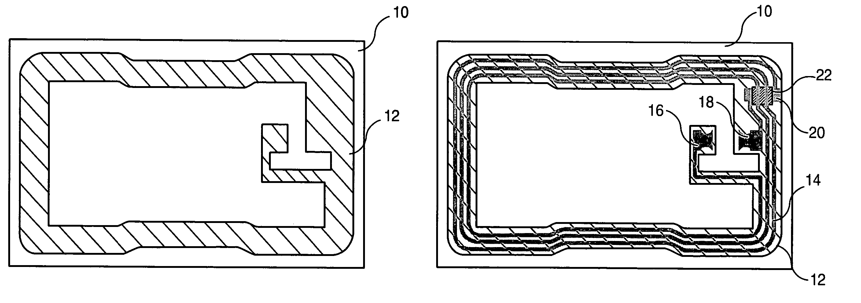
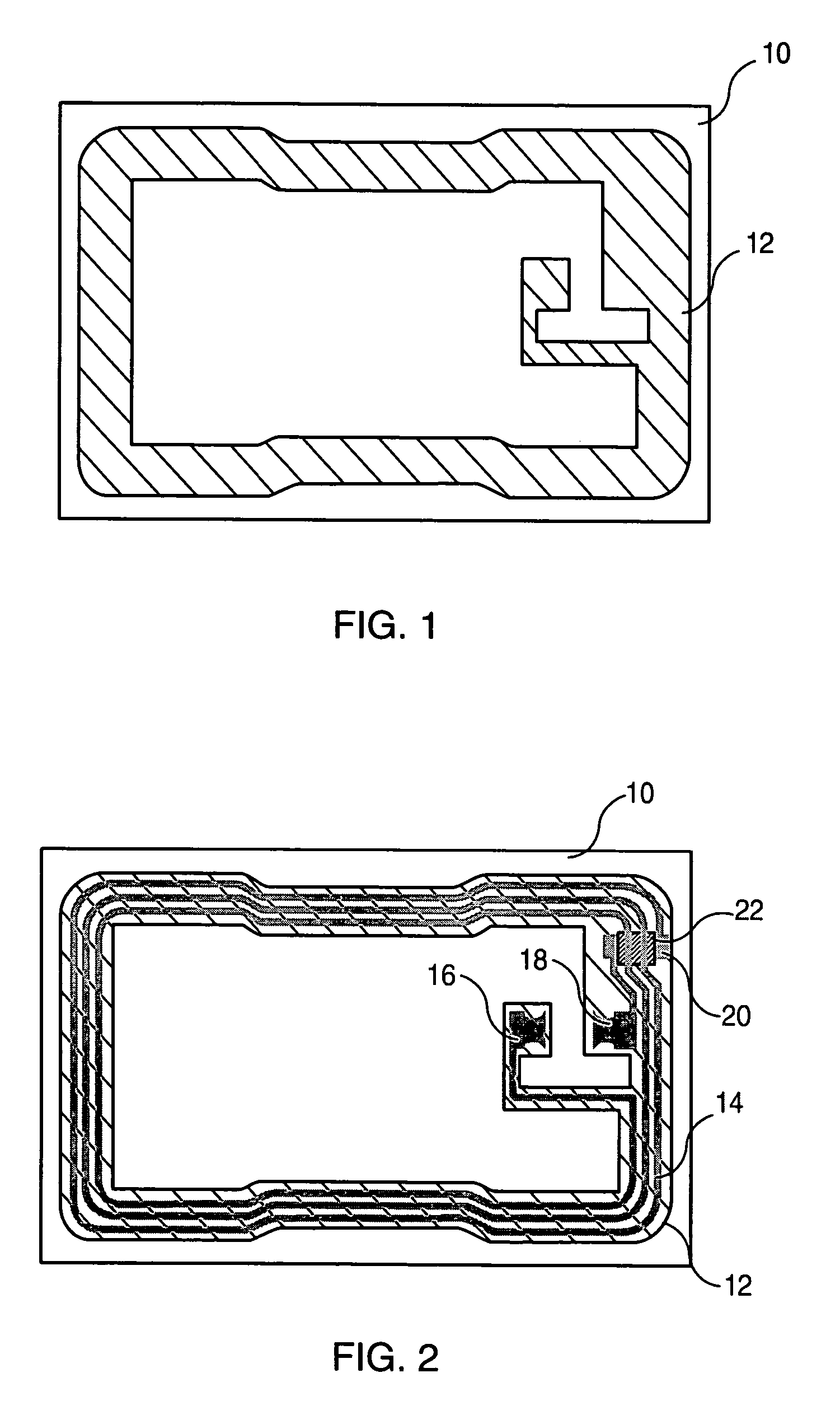
[0020]According to FIG. 1, resin is deposited on the antenna support 10 made of thermoplastic material of a hybrid contact-contactless smart card on a zone 12 corresponding to the location of the antenna and connection pads of the antenna with the module. The details of the shape of the zone 12 do not constitute a limitation for the invention, the main constraint being that the zone 12 defines the location where the conductive ink forming the turns and the connection pads of the antenna will be printed afterwards. Zone 12 is preferably slightly larger than the antenna's imprint as can be seen on the following FIGS. 2 and 5. The thickness of the resin layer applied is of the order of 5 μm.

[0021]According to a preferred embodiment of a hybrid contact-contactless smart card antenna shown in FIG. 2, the antenna is screen printed on zone 12 of the antenna support 10 in several passes and in reverse order compared with the standard screen printing method. The first pass consists in screen...


PUM

PropertyMeasurementUnit
pressureaaaaaaaaaa
temperatureaaaaaaaaaa
softening temperatureaaaaaaaaaa

Abstract

A method for making a hybrid contact / non-contact or non-contact smart card which includes a support (10,11) on which is produced an antenna, two card bodies (32, 42, 34, 44) on either side of the support, each of the card bodies including at least one thermoplastic layer, and one chip (30) or module connected to the antenna. The method includes the following steps: depositing a layer of a material having a major amount of resin on a predetermined zone (12,13) of the antenna support; making the antenna which includes screen-printing turns (14.15) and two connection pads (16,18,17,19) of conductive polymer ink on the zone previously produced on the support, and subjecting the support to a heat treatment to cure the ink.

Description

TECHNICAL FIELD[0001]The present invention relates to hybrid contact-contactless smart card or contactless smart cards antennae manufacturing methods and relates particularly to a manufacturing method for the antenna of a smart card on a thermoplastic support and the smart card obtained by said method.BACKGROUND[0002]Contactless smart cards or hybrid contact-contactless smart cards are equipped mainly with an antenna embedded in the card and an electronic module connected to the antenna. These cards allow the exchange of information with the outside by remote, and therefore contactless, electromagnetic coupling, between their antenna and a second antenna located in the associated reader. In the case of a hybrid card, this exchange may also be done by electrical transmission of data between the flush contacts of the card's electronic module and the contacts of a reader's reading head into which the card is inserted. These cards are now used in many sectors. In this manner, in the tra...

Claims


Application Information

Patent Timeline
Patent Type & Authority Patents(United States)
IPC IPC(8): G06K19/06B32B37/04B32B37/18G06K19/077
CPCB32B37/04B32B37/185G06K19/07783G06K19/0773G06K19/07749G06K19/07779B32B2305/342B32B2425/00G06K19/077G06K19/07
Inventor BENATO, PIERRE
Owner ASK SA (FR)
Why Eureka
Try Eureka