Loudspeaker with undulated membrane

a technology of undulating membrane and loudspeaker, which is applied in the field of loudspeakers, can solve the problems of speaker performance and diaphragm movement instability, and achieve the effect of stable membrane movement during use and small height without deteriorating sound performan

Active Publication Date: 2009-10-06
PSS BELGIUM +1
View PDF2 Cites 9 Cited by
  • Summary
  • Abstract
  • Description
  • Claims
  • Application Information

AI Technical Summary

Benefits of technology

[0006]It is an object of the invention to provide a loudspeaker which can be given a small hei

Problems solved by technology

For this reason, there arise problems relating to the speaker's performance if a shallow speaker, i.e. a speaker having a small height, is required in certain applications.
Although the speaker known from JP-A 54-6523 comprises means for solving the problem rela

Method used


Image

  • Loudspeaker with undulated membrane
  • Loudspeaker with undulated membrane
  • Loudspeaker with undulated membrane

Examples


Embodiment Construction

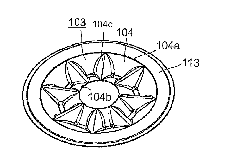
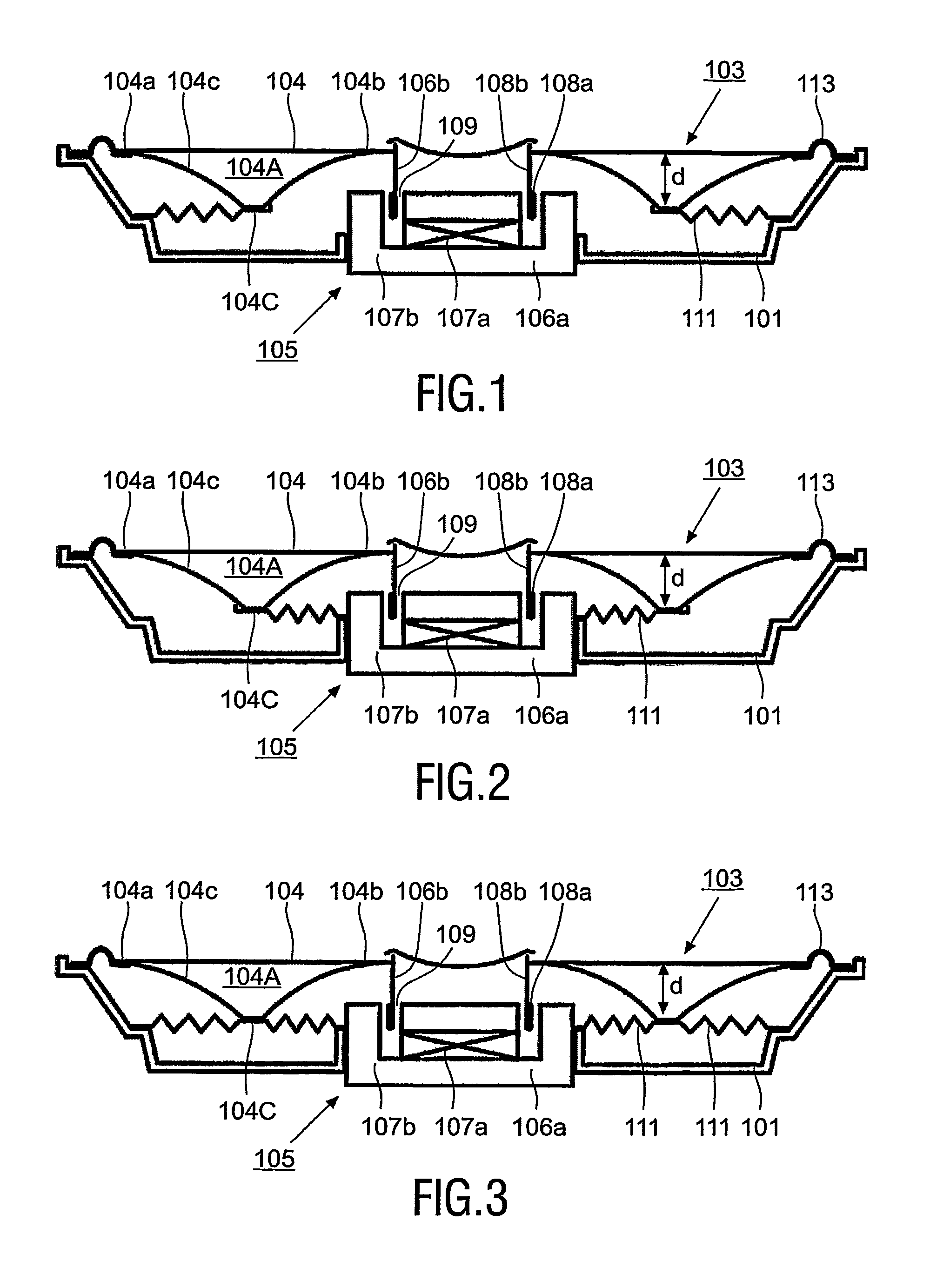
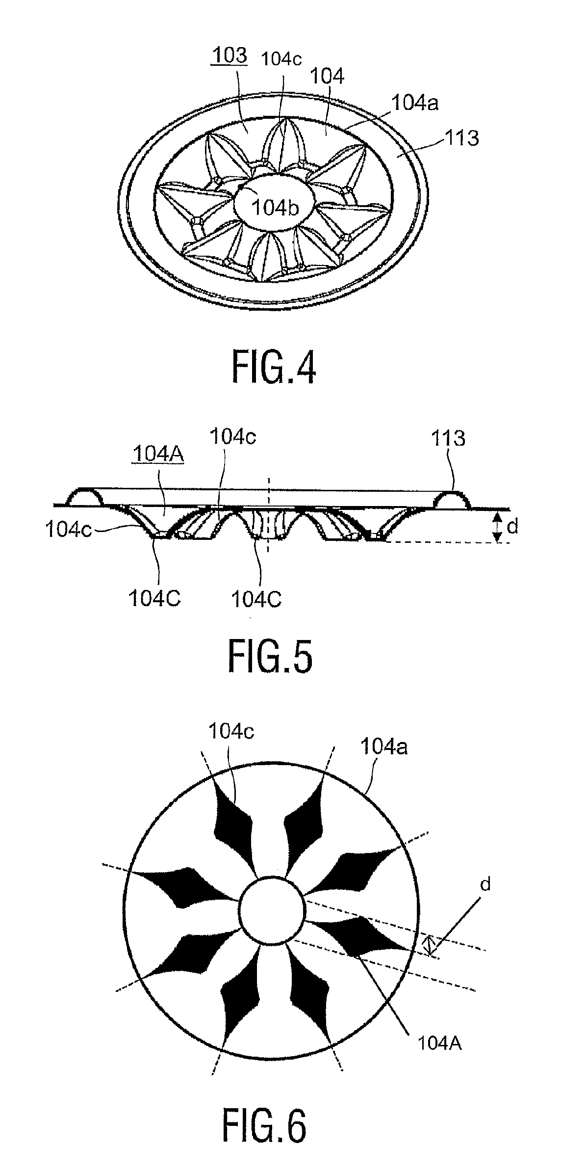
[0029]The loudspeakers depicted in FIGS. 1 to 3 are provided with a frame 101, a membrane 103 and an electromagnetic drive unit 105. In principle, the membrane 103 has a flat membrane body 104 provided with a flat outer circumferential edge 104a and a flat inner circumferential edge 104b and is provided with a pattern of radial folds 104c, which pattern extends over the surface of the membrane 104, viewed in circumferential direction. The folds 104c have a depth (d) which increases from the outer edge 104a towards a middle area 104A formed by a ring-shaped zone between the edges 104a and 104b, and from the inner edge 104b towards this area 104A, whereby the maximum depth (d) is located in the area 104A. The folds 104c are provided with faces 104C in the area 104A. The membrane body 104 may be made of e.g. paper, particularly reinforced paper. The drive unit 105 comprises a stationary part 106a and a movable, i.e. translatable, part 106b. The stationary part 106a is secured to the fr...


PUM


Abstract

A loudspeaker provided with a frame (101), a membrane (103) and a drive unit (105). The membrane has an outer circumferential edge (104a) suspended from the frame and an inner circumferential edge (104b). The drive unit has a stationary part (106a) secured to the frame and a translatable part (106b) provided with a coil support (108b) secured to the inner circumferential edge of the membrane. The membrane includes a membrane body (104) which, viewed in a circumferential direction, has a pattern of folds radially extending between the inner circumferential edge and the flat outer circumferential edge of the membrane. The folds have a depth (d), which increases from the edges (104a, 104b) towards an area (104A) situated between both edges. In this area, the folds are provided with faces (204C), to which a spider (111) of the loudspeaker is secured. This loudspeaker combines a small height with a large stroke of the membrane.

Description

FIELD OF THE INVENTION[0001]The invention relates to a loudspeaker which is provided with a frame, a membrane and a drive unit.BACKGROUND OF THE INVENTION[0002]Such speakers are generally known. FIG. 8 of the accompanying drawing shows a known loudspeaker. This speaker has a frame (1), a membrane (2) and an electromagnetic drive unit (4). The membrane is formed by a conical body (2a) and has a flat outer circumferential edge (2b) and a flat inner circumferential edge (2c). The drive unit is provided with a stationary part (4a) and a movable part (4b). The stationary part, which includes a permanent magnet and a magnetic yoke, is secured to the frame. The movable part includes a voice coil and a cylindrical coil support (4b1). At its outer circumferential edge, the membrane is connected to the frame by means of a flexible suspension (6) and at its inner circumferential edge, it is adhered to the coil support, which in its turn is connected to the frame by means of a spider (8).[0003]...

Claims


Application Information

Patent Timeline
IPC IPC(8): H04R7/02H04R9/06H04R7/14H04R9/04
CPCH04R7/14H04R9/045H04R7/00H04R9/00H04R9/04
Inventor CORYNEN, DAVID MAGDA EDDY
Owner PSS BELGIUM
Why Eureka
Try Eureka