Motor structure with built-in lens

a technology of motor structure and lens, which is applied in the direction of printers, instruments, camera focusing arrangement, etc., can solve the problems of increasing volume, adding cost and complexity to the camera lens module, etc., and achieves stable and accurate movement, high abrasion resistance, and reduced friction between the rotor and the bearing layer.

Inactive Publication Date: 2009-10-06
HON HAI PRECISION IND CO LTD
View PDF15 Cites 4 Cited by
  • Summary
  • Abstract
  • Description
  • Claims
  • Application Information

AI Technical Summary

Benefits of technology

[0004]According to a preferred embodiment of the present invention, a motor structure with a built-in lens includes a lens mount, a motor received in the lens mount, and a lens unit received in the lens mount and driven by the motor to telescopically move along an axial thereof. The motor includes a stator and a rotor being rotatably received in the stator. A narrow gap is defined between an inner surface of the stator and an outer surface of the rotor. A bearing layer is filled in the gap of the motor to avoid swing of the rotor during rotation thereof. The bearing layer is made of high abrasion resistant materials or self-lubricating materials. By this way, friction generated between the rotor and the bearing layer can be greatly reduced. The lens unit is threadedly engaged with the rotor. When the rotor rotates, the lens unit has a linearly telescopic movement relative to the motor mount by a guidance of a top cover. By the bearing layer, the motor can drive the lens unit to have stable and accurate movement.

Problems solved by technology

Since the drive motor is located at the outside of the camera lens mount, the drive motor requires extra transmission parts in the camera lens mount to drive the telescopic lens to move, which often encounters the following drawbacks.
The extra transmission parts, which drive the telescopic lens to move inside the camera lens mount, add cost and complexity to the camera lens module and increase the volume thereof.

Method used


Image

  • Motor structure with built-in lens
  • Motor structure with built-in lens
  • Motor structure with built-in lens

Examples


Embodiment Construction

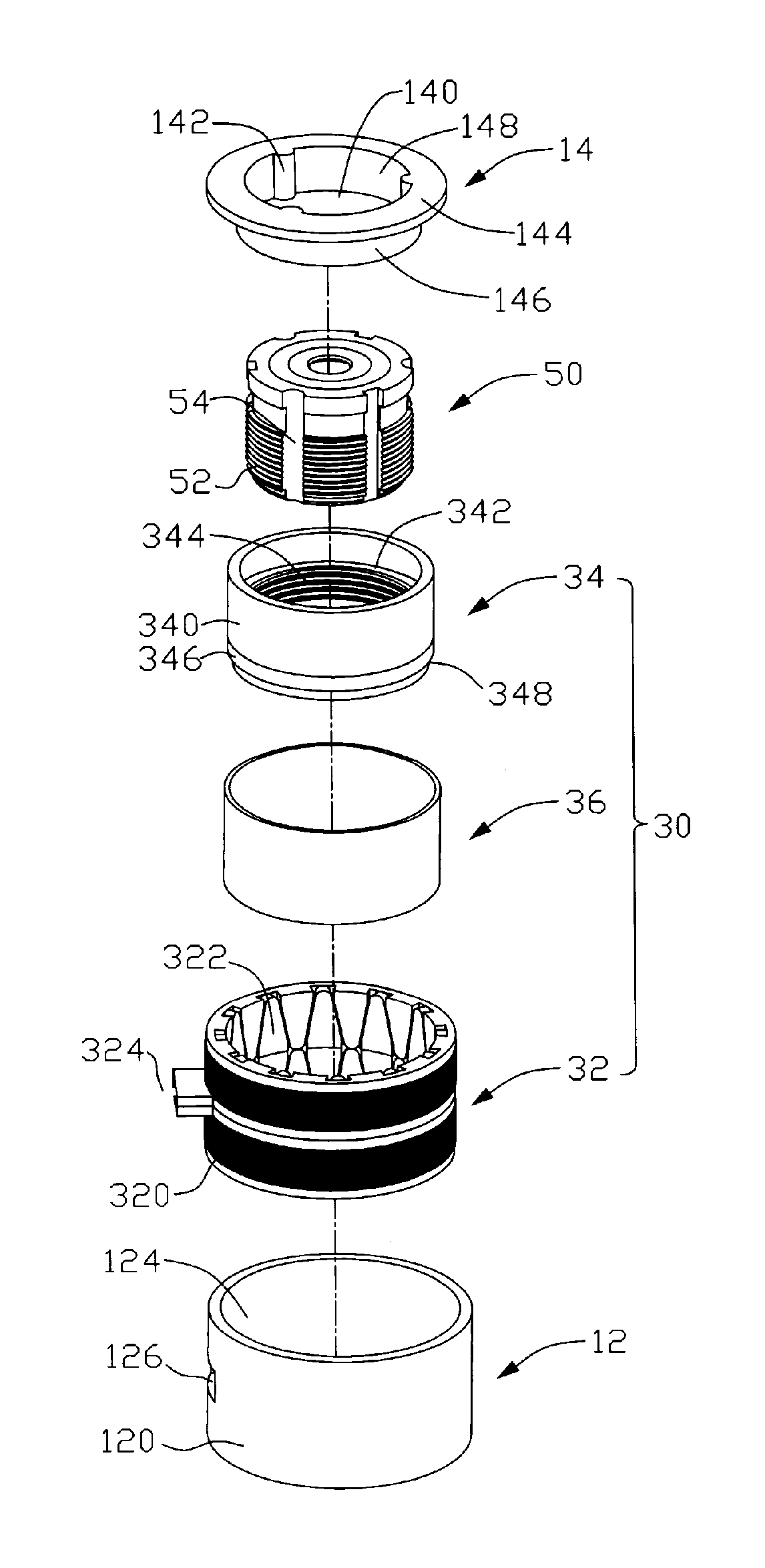
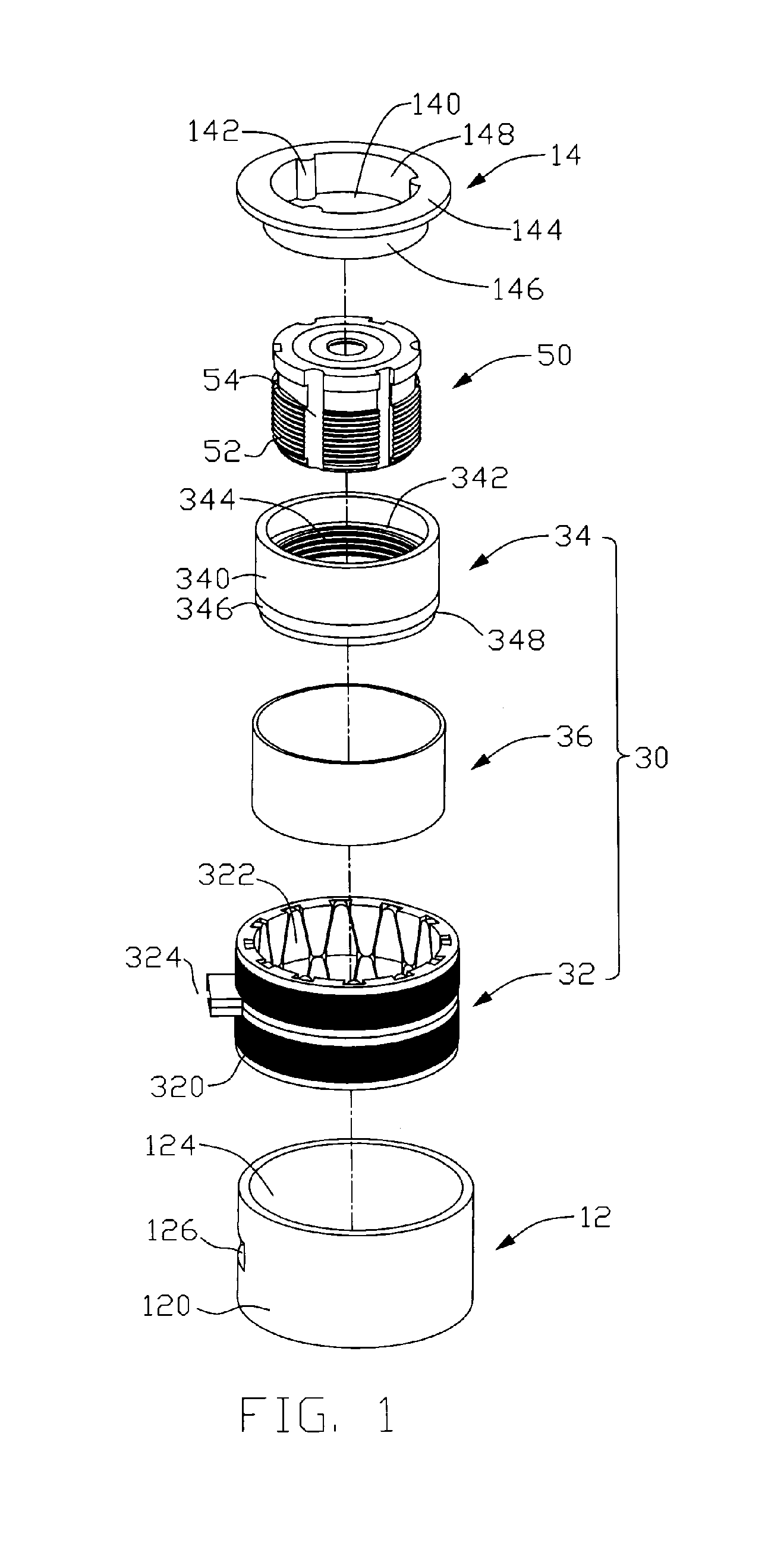
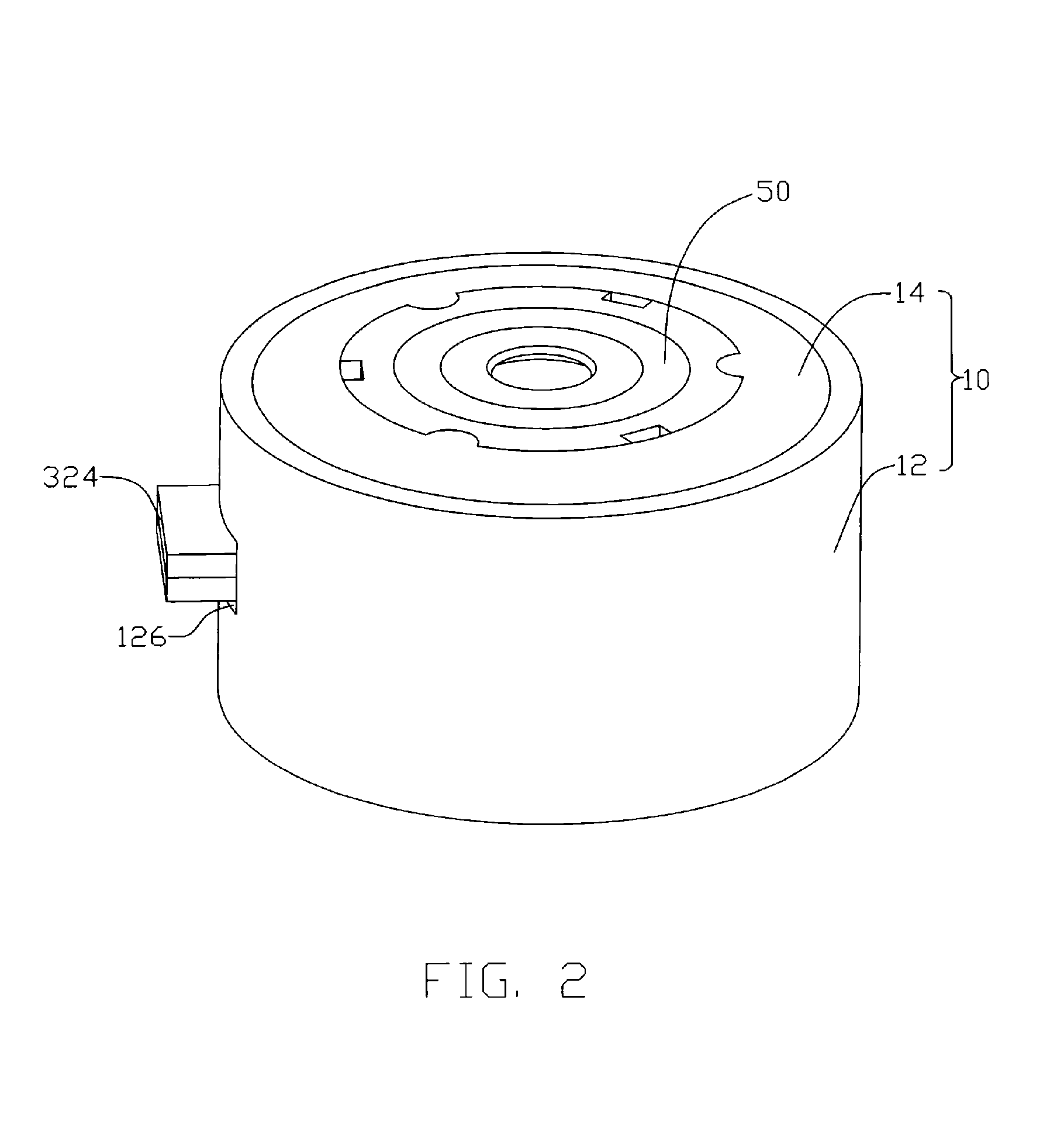
[0011]Referring to FIGS. 1 through 3, a motor structure with built-in lens according to a preferred embodiment includes a lens mount 10, a motor 30 received in the lens mount 10, and a lens unit 50 being drivable by the motor 30.

[0012]The lens mount 10 includes a bottom cover 12 and a top cover 14 located above and facing the bottom cover 12. The bottom cover 12 includes a ring-shaped basewall 122 and a sidewall 120 extending perpendicularly and upwardly from an outer-periphery of the basewall 122. An opening 124 is defined in the sidewall 120 above the basewall 122 for receiving the top cover 12. The top and bottom covers 14, 12 cooperatively define a column-shaped space (not labeled) therein when the top and bottom covers 14, 12 are assembled together. A passage 126 is defined in the sidewall 120 of the bottom cover 12 for extension of wires 324 of the motor 30 therethrough to connect the motor 30 with a power source (not shown). Circular hole 128 is defined in a central portion o...


PUM


Abstract

A motor structure with a built-in lens includes a lens mount (10), a motor (30) received in the lens mount, and a lens unit (50) received in the lens mount and driven by the motor to telescopically move along an axial thereof. The motor includes a stator (32) and a rotor (34) being rotatably received in the stator. A narrow gap is defined between an inner surface of the stator and an outer surface of the rotor. A bearing layer (36) is filled in the gap of the motor to avoid swing of the rotor during rotation thereof. The lens unit threadedly engages with the rotor, whereby when the rotor rotates, the lens unit has a linearly telescopic movement relative to the lens mount.

Description

FIELD OF THE INVENTION[0001]The present invention relates generally to drive source of camera lens, and more particularly to a drive source with built-in camera lens.DESCRIPTION OF RELATED ART[0002]The traditional structure of autofocus camera lens affixes a drive motor on an outside of a camera lens mount and, through the connection of transmission parts, the drive motor drives the telescopic lens in telescopic motion. Since the drive motor is located at the outside of the camera lens mount, the drive motor requires extra transmission parts in the camera lens mount to drive the telescopic lens to move, which often encounters the following drawbacks.[0003]Since the drive motor is affixed to the outside of the camera lens mount, the structure of the camera lens is asymmetrical, which affects the spatial disposition of the camera lens module consisting of the camera lens mount and the telescopic lens. The extra transmission parts, which drive the telescopic lens to move inside the cam...

Claims


Application Information

Patent Timeline
Patent Type & Authority Patents(United States)
IPC IPC(8): G03B3/10H02K37/12G03B3/00G03B30/00
CPCG03B17/04G02B7/08
Inventor HSIAO, CHENG-FANGSHIH, WUN-CHANGHUANG, CHING-HSINGHONG, CHIEN-LONG
Owner HON HAI PRECISION IND CO LTD
Why Eureka
Try Eureka