Power adjustable wrench

a technology of adjustable wrenches and wrenches, which is applied in the field of adjustable wrenches, can solve the problems of insufficient driving force, affecting the working efficiency, and inability to drive stable, and achieves the effects of compact gear transmission mechanism arrangement, compact structure and small siz

Inactive Publication Date: 2009-10-13
NINGBO GREAT WALL PRECISION INDAL
View PDF6 Cites 3 Cited by
  • Summary
  • Abstract
  • Description
  • Claims
  • Application Information

AI Technical Summary

Benefits of technology

[0007]The technical problem for this invention to solve is to provide a power adjustable wrench with reducing gear transmission, stable adjustable jaw and without buffering device or high production cost.
[0010]As optimization, the said gear reducer comprises a first couple of coaxial gears including a second bevel gear and a third gear both connected by a rotor shaft, a second couple of coaxial gears including a forth gear and a fifth gear, and a worm gear; the electromotor which is inside the wrench body and is parallel to the length direction of the wrench body has a first bevel gear fixed with a driving a shaft of the electromotor; the first bevel gear is in gear with the second bevel gear, the third gear is in gear with the forth gear, the fifth gear is in gear with the worm gear. It is the compact structure and small size and ensures easy installation.
[0011]As a further improvement, the said rotor shaft is ratably fixed on a bracket inside the wrench body, the second couple of coaxial gears is ratably assembled at a minor axis hole on an inner wall of the wrench body by a minor axis, the worm integrates with the worm gear via a major axis and is rotatably assembled at the major axis hole on the inner wall of said wrench body, which facilitates the production and assembly.
[0013]As a further improvement, the wrench body comprises the main body, an upper cover and a lower cover for enclosing the gear transmission mechanism, electromotor and the switch of the power supply, the main body is provided with a front through hole for containing the electromotor and gear transmission mechanism and a rear through hole for containing the switch and the power supply, the minor axis hole is equipped at the front end of the upper cover, which facilitates the production and assembly.
[0014]As a very beneficial improvement, the switch is a switch for controlling positive and reverse rotation of the electromotor, which comprises a button with two return springs at both ends respectively, the button has two parallel conductive contact blocks on the bottom of the button, a circuit board having metal foils on face and back sides thereof is located under the conductive contact blocks, the face metal foil forms a pair of output contact pieces at the upper part, a pair of input contact pieces at the middle and a pair of transmission pieces at the lower part, which are arranged in parallel, while a pair of input terminals are riveted on the side of the circuit board against the button, the back metal foil forms a pair of connecting pieces for connecting the pairs of input terminals with said pair of input contact pieces, forms a pair of connecting pieces for reverse switching connection of the transmission contact pieces with the output contact pieces, allowing an output to be positive when the button moves upwards and an output to be reverse when the button moves downwards. This structure makes the switch very light and thin, appliable to be installed in the long and narrow space inside the spanner body, it is easily assembled and produced low cost.
[0017]Compared with existing technologies, this invention has advantages as follows: compact structure, compact arrangement of gear transmission mechanism, small size, low cost of manufacture, allowing the application of speed change gear with three pairs of reduction or more pairs in the long and narrow through hole, which makes the advancing speed of the adjustable jaw optimized, the revolutions of the electromotor reduced and the electric work efficiency improved, the moving speed is stable with low noise, one end of the worm is fixed when the worm is rotated to the end, no buffering mechanism is required; the circuit adopts the switch for positive and reverse rotation, which can change the rotation direction of the electromotor, moreover the switch can only be powered on with external force, which avoids damages of the device due to certain mistaken operations, its light and thin structure facilitates the operation and installation and lowers the cost.

Problems solved by technology

This structure has the following deficiencies in practical application: First, the fingers cannot access screw caps in some special locations of machines, or even if the fingers can access them, the operation locations will obstruct the line of sight, which may cause inconvenience for manual operation and result in improper size of jaw, leading to permanent damage of screws; second, manual operation has limited force and needs space for operation, during the design, problems like excessive interval between the worm and the adjustable jaw may be caused, which may cause the damage of the screw cap corners and make them incapable of being screwed, resulting in losses and troubles; finally, manual operation needs great efforts and has poor effect, which will greatly impact the working efficiency.
This design needs to be improved in the following aspects: first, because the electromotor is vertical to the length of the spanner, the head of the spanner is too large to be used conveniently; second, although the reduction gear set is provided, the electromotor still rotates at high speed, during fast driving, the driving force is insufficient and the driving is not stable; third, during fast driving, the worm may be damaged without a buffering device, which may influence the service life of the electromotor; fourth, too fast speed will result in small force, when screwing the screw cap, it will be flexible.
There is a similar patent: CN1868684A, which provided a limit pin, however, the advancing speed of the worm is still high and the head of the spanner is inevitably large.
Please refer to U.S. Pat. No. 6,477,921, which disclosed an electric adjustable wrench, which drives the worm by an electromotor via a belt or chain, however, due to the excessive rotating speed of the electromotor, the problems above still cannot be avoided, similarly, there are U.S. Pat. Nos. 6,966,242 and 4,512,221, because the belts and chains require large space of installation and are easily damaged, the electromotor needs to have high efficiency with a small size, which may cause increase of the cost.
Though great improvement has been made, the advancing speed of the worm is still too high, as the output power of said electromotor is rated, the force is still insufficient, and when screwing the screw cap, the worm is still subject to looseness; the electromotor produces large noise during the driving, and further improvements can be made.

Method used


Image

  • Power adjustable wrench
  • Power adjustable wrench
  • Power adjustable wrench

Examples


embodiment

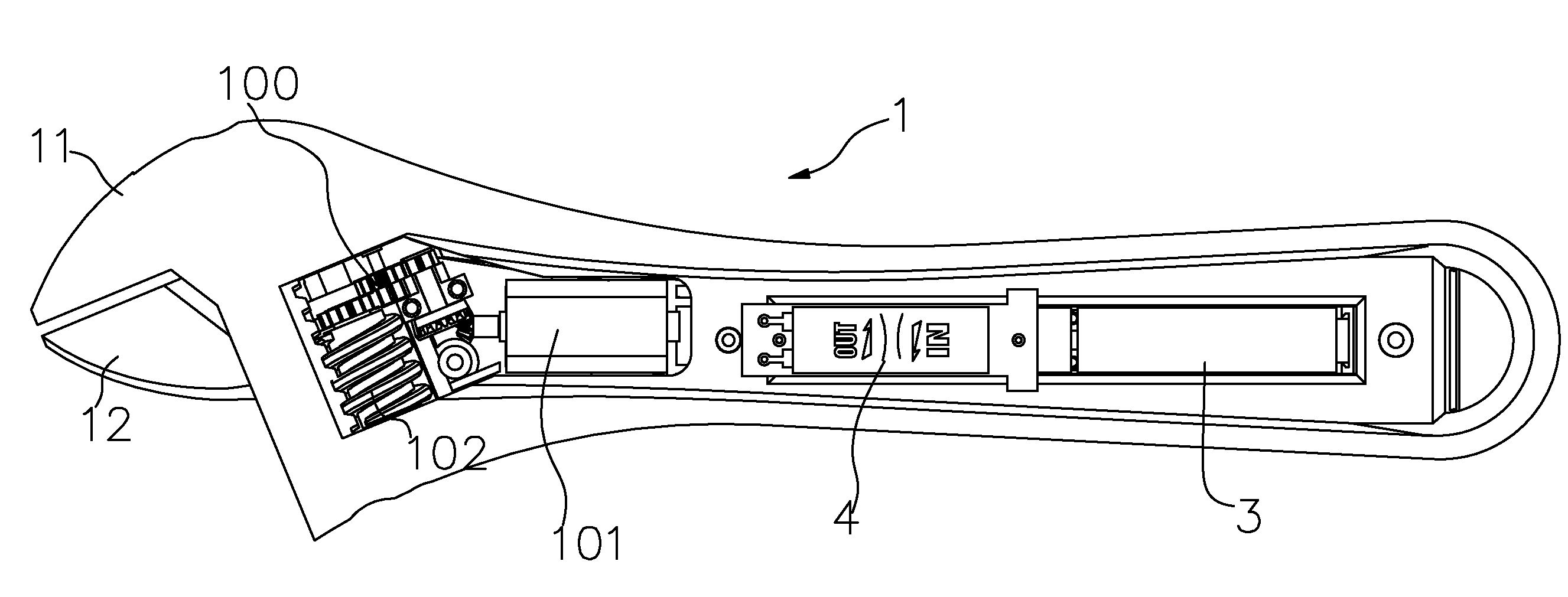
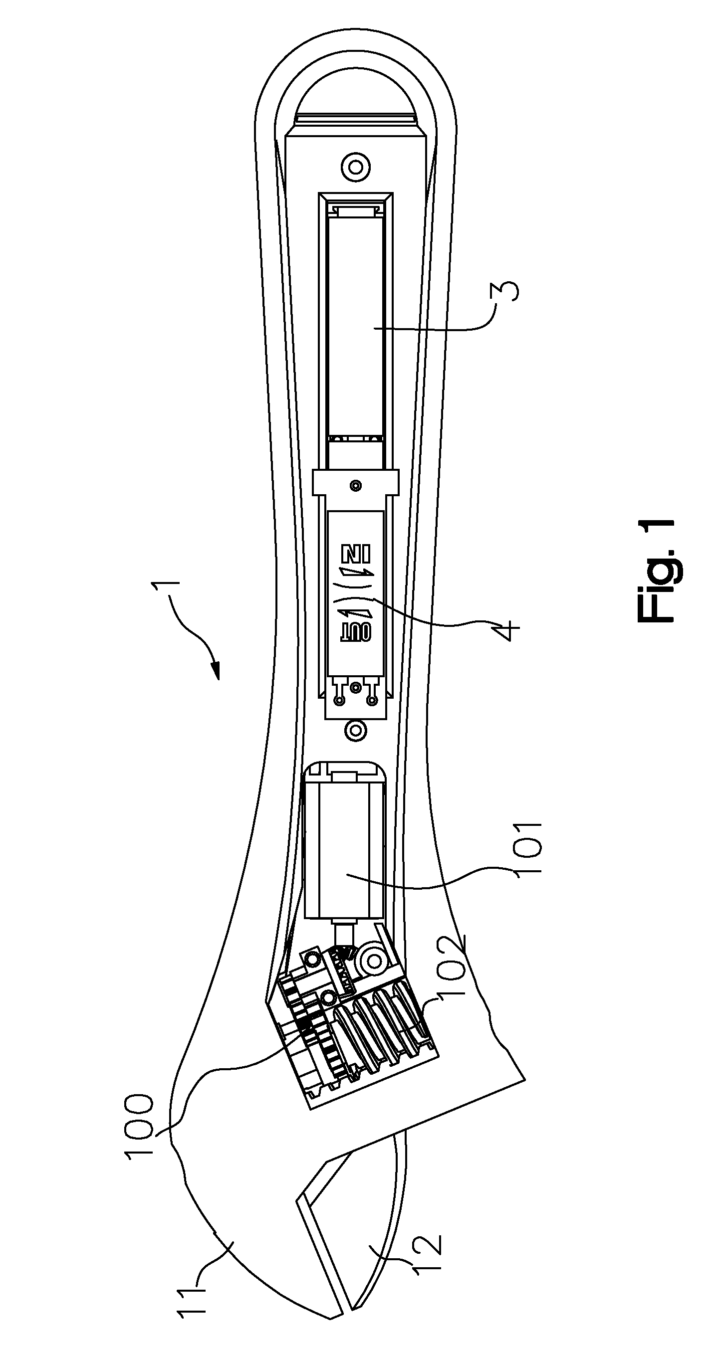
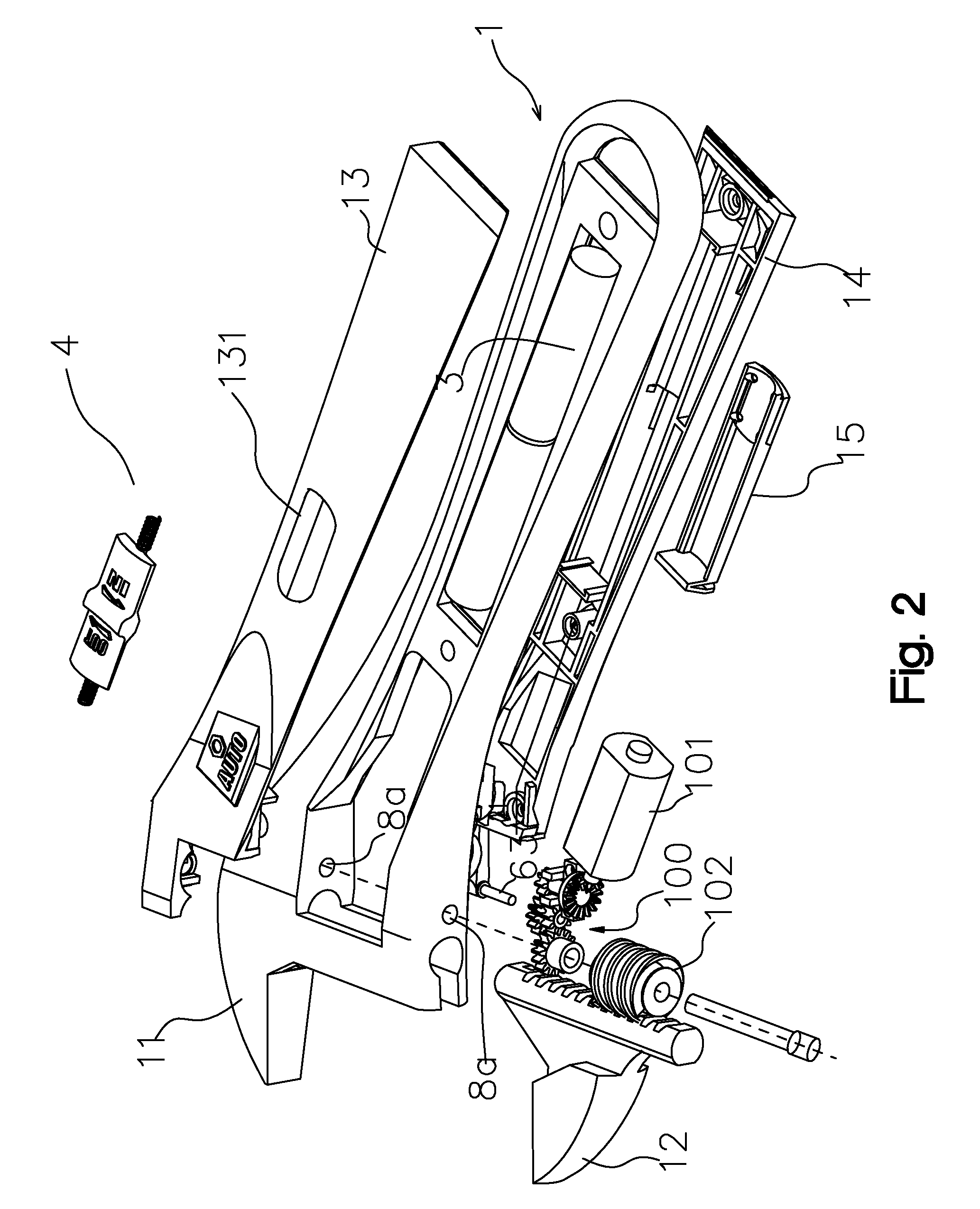
[0030]see FIG. 1 and FIG. 2, the power adjustable wrench according to this embodiment also comprises: the wrench body 1, the adjustable jaw 12, the electrometer 101, the power supply 3, the switch 4 and the gear transmission mechanism 100, a fixed jaw 11 being provided at the front end of the wrench body 1, said fixed jaw 11 is connected with said adjustable jaw 12 to form the size of jaw that can be adjusted, the worm gear at the bottom of said adjustable jaw 12 is engaged with the worm 102 to drive said adjustable jaw 12 back and forth, the output end of said gear transmission mechanism 100 is engaged with said worm 102 and said electromotor 101, power supply 3 and switch 4 form the driving control circuit, this embodiment adopts dry batteries or solar cells as the power supply 3, when solar cells are used, the solar energy panel should be installed on the surface of said wrench body 1.

[0031]See FIG. 3 and FIG. 4, the wrench body 1 comprises the main body 1a, the upper cover 13 an...


PUM


Abstract

An electric adjustable spanner comprises a spanner body, an adjustable jaw, a driving control circuit including an electromotor, a power supply, a switch and a gear transmission mechanism. the switch is a switch for controlling positive and reverse rotation of the electromotor. The switch comprises a button with two return springs at both ends respectively; the button has two parallel conductive contact blocks on the bottom of the button. A circuit board having metal foils on face and back sides thereof is located under the conductive contact blocks. The face metal foil forms a pair of output contact pieces, a pair of input contact pieces and a pair of transmission pieces at the lower part, and a pair of input terminals is riveted on the side of the circuit board against the button. When the button moves upward the output is positive and when the button moves downwards the output is reverse.

Description

CROSS REFERENCE TO THE RELATED PATENT APPLICATION[0001]This patent application claims the priorities of the Chinese patent application No. 200710070669.8, filed on Aug. 31, 2007 and Chinese patent application No. 200820083891.1, filed on Mar. 6, 2008, which are incorporated herein by reference.FIELD OF THE INVENTION[0002]This invention relates to a power adjustable wrench, and more particular to an electric adjustable wrench that can be driven by electromotor to adjust the size of jaw.BACKGROUND OF THE INVENTION[0003]An ordinary adjustable wrench includes the wrench body and an adjustable jaw, a fixed jaw is provided at the front end of the wrench body, the fixed jaw is connected with adjustable jaw to form the size of jaw that can be adjusted, a worm is provided at the bottom of the adjustable jaw to drive the adjustable jaw back and forth, the jaw can be moved back forth by screwing the worm with your thumb. This structure has the following deficiencies in practical application: F...

Claims


Application Information

Patent Timeline
Patent Type & Authority Patents(United States)
IPC IPC(8): B25B21/00B25B13/16
CPCB25B13/14
Inventor HUANG, ZHONGHUATIAN, YEQINGZOU, JIAMINGZHU, WENJIANG
Owner NINGBO GREAT WALL PRECISION INDAL
Why Eureka
Try Eureka