
RFID and low resolution CCD sensor based positioning system

a positioning system and low-resolution technology, applied in the field of rfid and low-resolution ccd sensor based positioning system, can solve the problems of positioning errors, less than operational optimal, and high installation cost involved in the installation of tape, and achieve the effect of accurately assessing the position of the moveable platform

Inactive Publication Date: 2009-10-13
OTIS ELEVATOR CO
View PDF29 Cites 33 Cited by
  • Summary
  • Abstract
  • Description
  • Claims
  • Application Information

AI Technical Summary

Benefits of technology

The present invention provides a system and method for low-cost and high-performance absolute position referencing for elevators and other conveyances. The system uses RF ID sensing technology and CCD image processing to accurately assess the position of a moveable platform. The method involves using RF tags and visual markers affixed to fixed positions, receiving coded information from the RF tags, imaging the visual markers with an optical device, performing image processing to identify the position of a visual cue, and combining the position of the visual cue with the coded information to determine the location of the moveable platform. The technical effects of the invention include improved accuracy and efficiency in elevator and conveyance positioning, reduced costs, and improved safety and reliability.

Problems solved by technology

Traditional optical elevator position reference systems (PRS) exhibit a number of attributes that render them less than operationally optimal.
A disadvantage of this system is that longitudinal expansions of the hoistway as well as the coded tape can cause positioning errors.
Another disadvantage of this system is the high installation costs involved in the installing the tape in the hoistway.
A disadvantage of this system is that it requires the use of two CCD cameras for generating elevator car position: one for reading the floor coarse position information and other one for fine positioning information.
If redundant systems have to provide data for the normal terminal stopping device (NTSD) and the emergency terminal stopping device (ETSD), the resultant system configuration would cause the production cost to be quite high.
Very fine coding patterns make the system susceptible to dirt and dust contaminations that may blur the coding patterns causing inaccurate car position information.
Another disadvantage is the great effort required for installing the reflector along the path in the elevator hoistway.

Method used


Image

  • RFID and low resolution CCD sensor based positioning system
  • RFID and low resolution CCD sensor based positioning system
  • RFID and low resolution CCD sensor based positioning system

Examples


Embodiment Construction

)

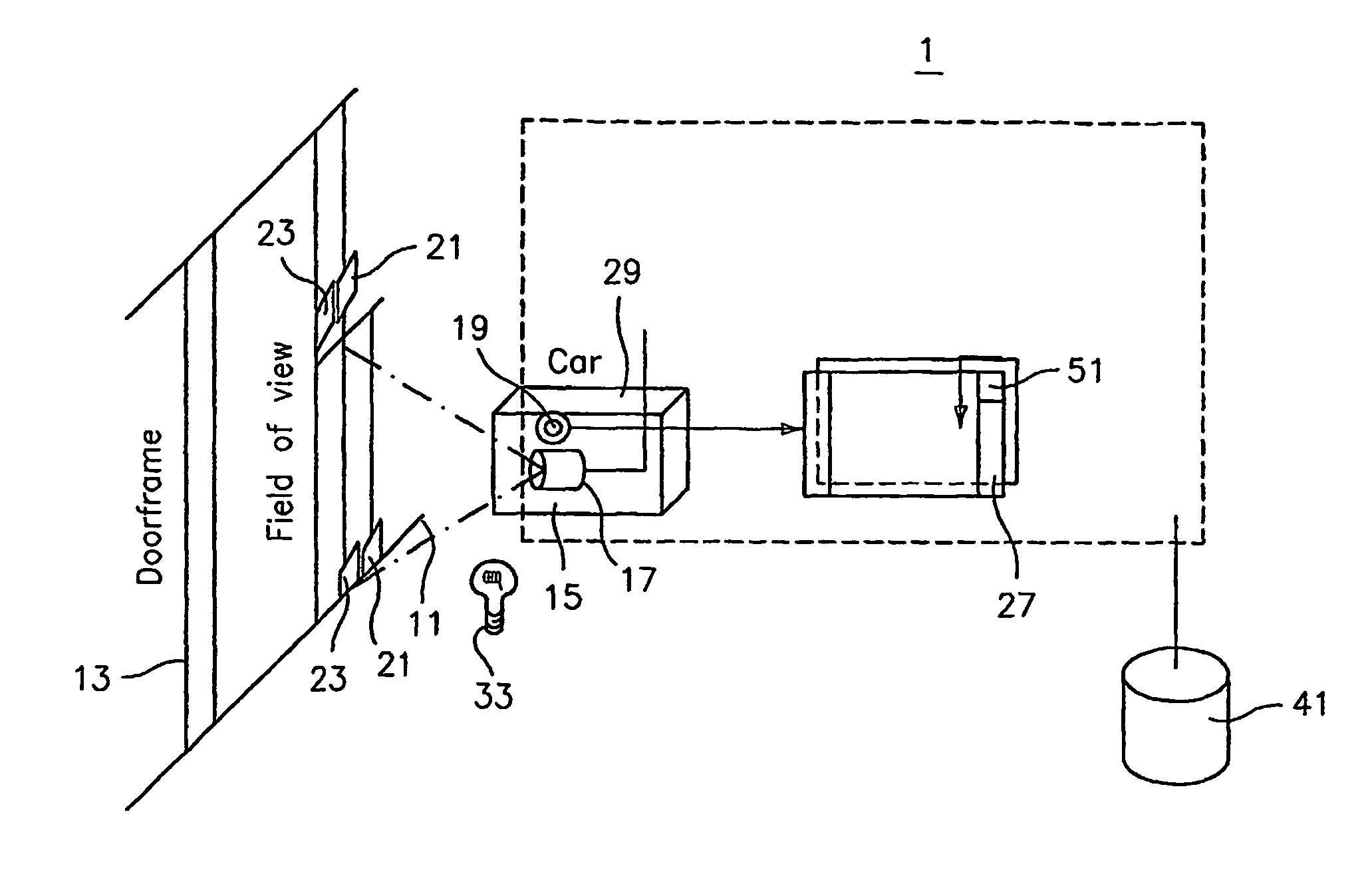
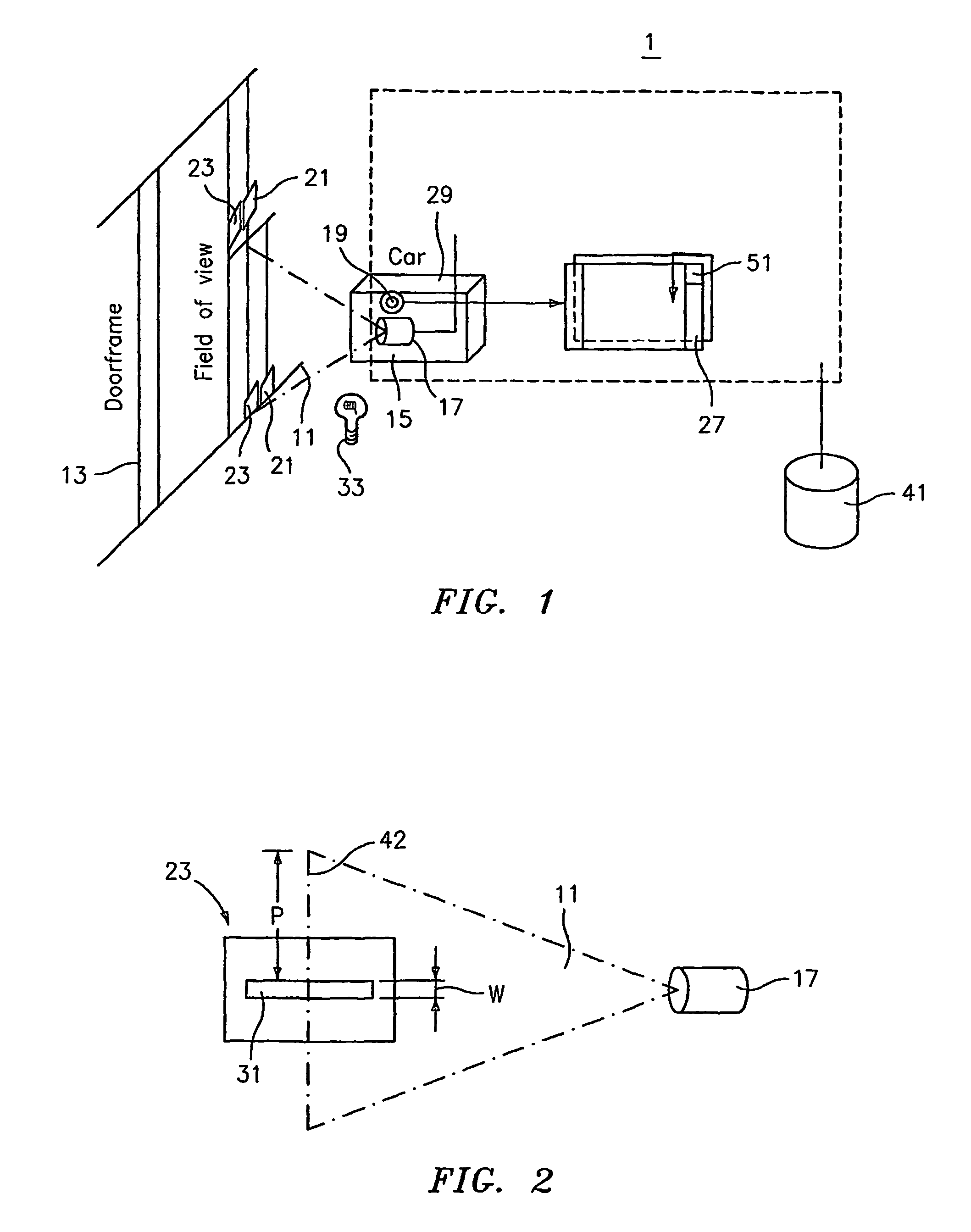
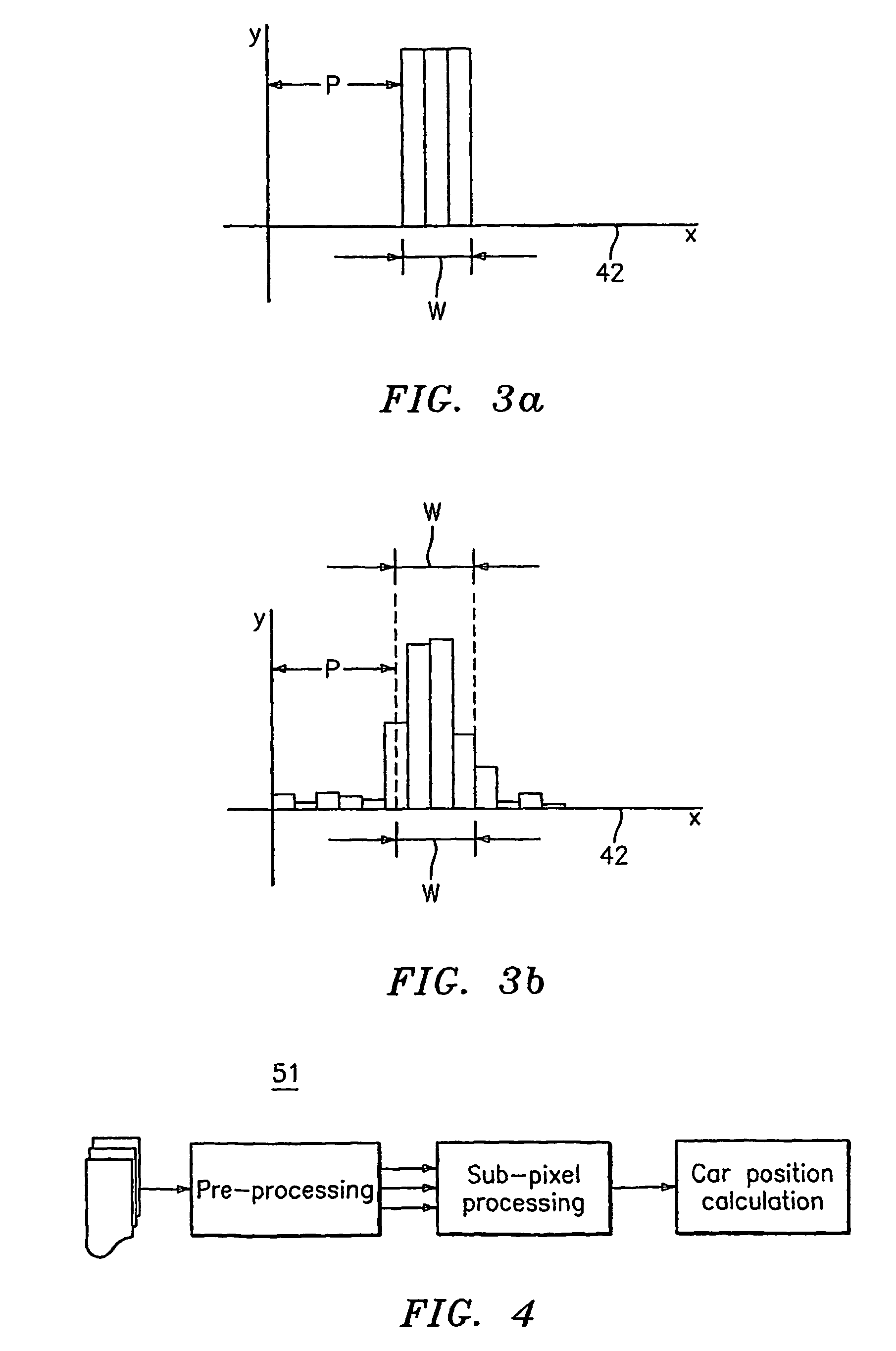
[0018]This invention centers on a positioning concept incorporating both RF technology and visual image processing to precisely locate the position of an elevator car. In a preferred embodiment, a number of RF tags encoded with location information are situated at known locations on and around the doorways lining an elevator hoistway. As the elevator comes into proximity with the RF tags, the encoded information is read by an RF reader attached to the elevator so as to determine the floor location of the elevator. Having determined the floor location of the elevator, a visual marker, preferably a horizontal line affixed to the hoistway doorframe at a precisely known position, is visually scanned. The scanned information is image processed to provide the precise position information of the elevator.

[0019]The major components of the PRS 1 of the present invention are shown with reference to FIG. 1. A number of radio frequency (RF) tags 21, coded to represent floor information and car...


PUM


Abstract

An apparatus and method for measuring a position of a moveable platform comprising a plurality of RFID tags encoded with location information situated at known locations and a plurality of visual markers situated at precise, known locations. An RF reader attached to a moveable platform reads the RFID tags to determine the approximate location of the platform. A camera apparatus attached to the moveable platform scans the visual marker. The scanned image is processed to provide the precise position information of the platform.

Description

BACKGROUND OF THE INVENTION[0001](1) Field of the Invention[0002]The present invention relates to a system and a method for low-cost and high-performance absolute position referencing for elevators and other conveyances. More specifically, the present invention relates to a system incorporating both RFID sensing technology and CCD image processing to accurately assess the position of a moveable platform.[0003](2) Description of Related Art[0004]A Positioning Reference System (PRS) is a component of an elevator control system that provides fast and accurate position measurement of a moveable platform, in particular an elevator car, in a hoistway. Traditional optical elevator position reference systems (PRS) exhibit a number of attributes that render them less than operationally optimal.[0005]One method of employing a PRS comprises using a coded tape defined by two tracks of openings cut along the length of the tape. The coded tape spans the entire longitudinal length of a hoistway. A...

Claims


Application Information

Patent Timeline
Patent Type & Authority Patents(United States)
IPC IPC(8): B66B1/36B66B3/02B66B1/34G06K
CPCB66B1/3492G06K7/10079
Inventor KANG, PENGJUOH, JAE-HYUKFINN, ALAN M.PENG, PEI-YUANHOOTSMANS, NORBERT A. M.
Owner OTIS ELEVATOR CO
Learn More