Inclusion of an anti-drain valve in viscous fan clutches

a technology of viscous fluid and clutch, which is applied in the direction of clutches, fluid couplings, couplings, etc., can solve the problems of wasting power and fuel, excessive fan noise, and complicated design

Active Publication Date: 2009-10-13
STANDARD MOTOR PROD INC
View PDF21 Cites 9 Cited by
  • Summary
  • Abstract
  • Description
  • Claims
  • Application Information

AI Technical Summary

Benefits of technology

[0022](i) check ball valve means provided at the second end of the discharge channel to prevent migration of fluid from the reservoir into the discharge channel.

Problems solved by technology

The return passageway has an inherent problem when the automobile is stationary for a long period of time (for example, over night parking or storage) in that the passageway may be facing an orientation below the horizontal point.
The probability for such orientation is as high as 50% and when the vehicle is then started any drained fluid in the working chamber will cause the fan clutch to engage resulting in excessive fan noise, wasted power and fuel inefficiency.
This design, though effective towards eliminating morning thickness, complicates the design by having to overcome the added resistance from the length of the channels.

Method used


Image

  • Inclusion of an anti-drain valve in viscous fan clutches
  • Inclusion of an anti-drain valve in viscous fan clutches
  • Inclusion of an anti-drain valve in viscous fan clutches

Examples


Embodiment Construction

)

[0030]In describing the preferred embodiment of the present invention, reference will be made herein to FIGS. 1-3B of the drawings in which like numerals refer to like features of the invention.

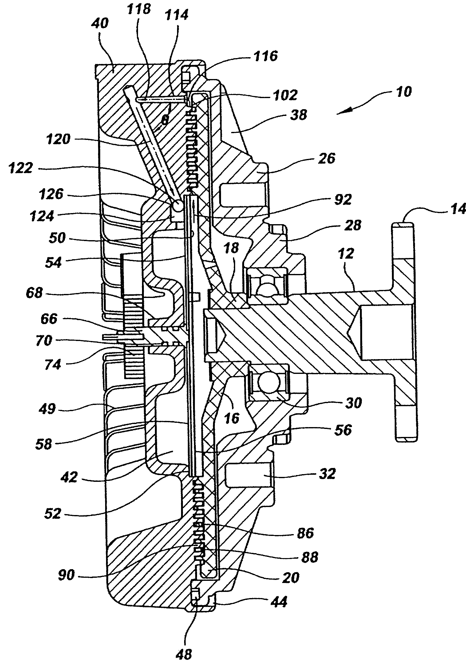
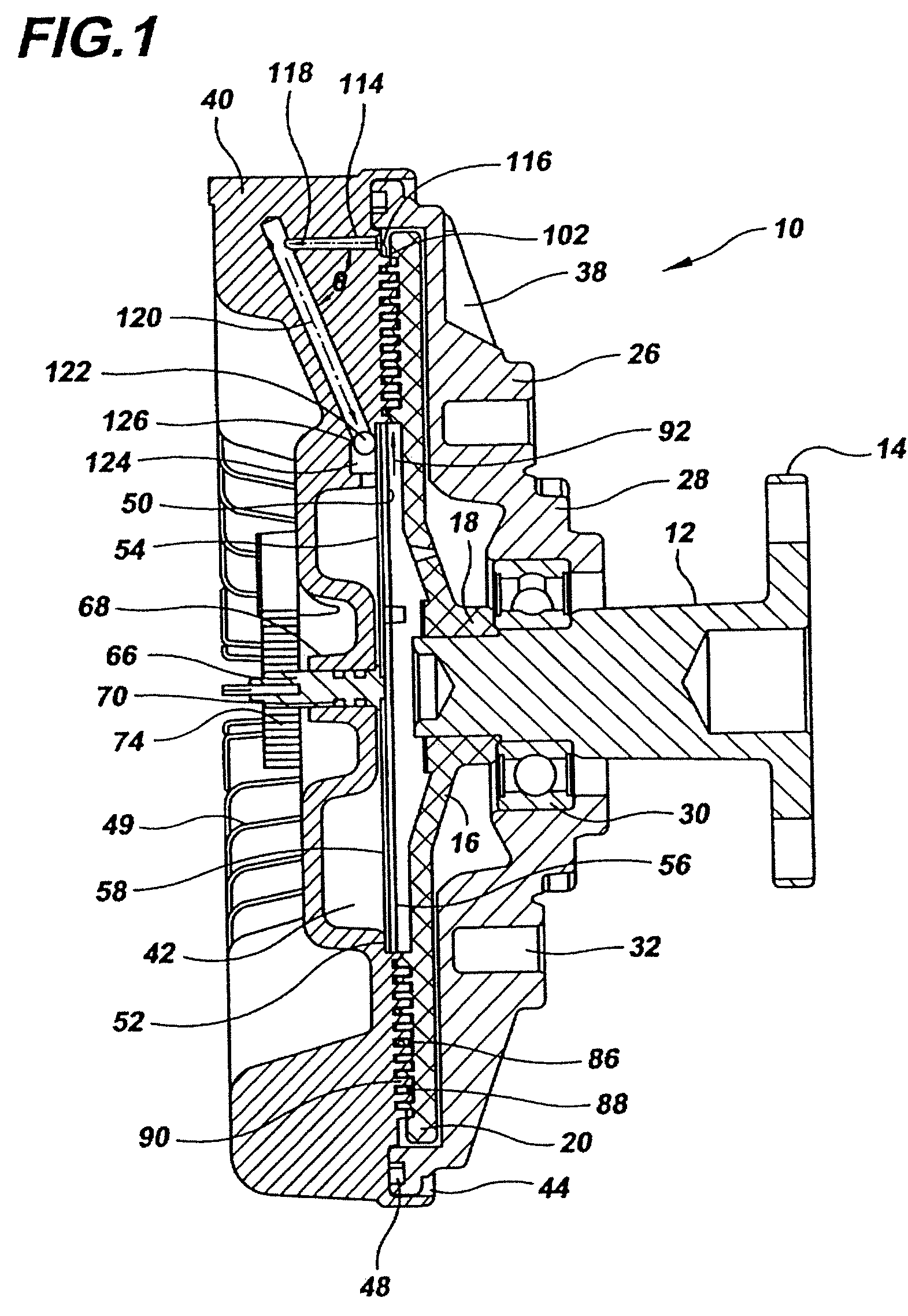
[0031]A viscous fluid clutch assembly indicated generally at 10 is illustrated in FIG. 1. The clutch assembly 10 includes a rotatably driven input shaft indicated generally at 12. The input shaft 12, which can be provided with multiple steps as illustrated in FIG. 1, preferably terminates at its first or innermost end in a flange 14. The flange 14 can be secured to a conventional engine-driven water pump pulley (not illustrated) to drive the clutch assembly 10 as described below,

[0032]A clutch plate indicated generally at 16 includes a central hub portion 18 and an annular disk portion 20. The central hub portion 18 is fixedly secured to the input shaft 12 to secure the clutch plate 16 onto the input shaft 12. In this construction, the rotational drive of the input shaft 12 is transferred to...


PUM


Abstract

A viscous fluid clutch assembly used in automobiles, SUVs, and trucks minimizes flow back of the cooling fluid from the reservoir towards the working chamber of the clutch when the vehicle is at rest and avoids excessive fan noise, wasted power and fuel inefficiency when a cold automobile engine is started. The clutch utilizes a discharge channel extending from the periphery of the working chamber to the reservoir and a specially designed ball check valve at the entrance to the reservoir which is open or closed depending on operation of the vehicle. The ball check valve is fluidly connected to the working chamber of the fluid clutch by a preferred articulated discharge channel which starts at the working chamber of the fluid clutch and ends at the reservoir of the fluid clutch.

Description

BACKGROUND OF THE INVENTION[0001]1. Field of the Invention[0002]The present invention relates to viscous fluid fan clutches such as clutches used in the automotive industry for controlling the amount of torque transmitted to a radiator cooling fan as a function of the temperature of a coolant fluid and, in particular, an anti-flowback check valve for the viscous fluid clutch which minimizes flowback of the viscous fluid from a reservoir to the working chamber of the fan clutch when the automobile is not being used and avoids excessive fan noise, wasted power and fuel inefficiency when a cold automobile engine is started.[0003]2. Description of Related Art[0004]Automobile fan clutches typically are “on-off” and “modulating” type devices and couple the cooling fan to the water pump. A fan clutch is activated by moving a viscous fluid in the clutch, typically, dimethyl-silicone from a storage chamber (reservoir) to a working chamber which couples a driving member to a driven member. Th...

Claims


Application Information

Patent Timeline
Patent Type & Authority Patents(United States)
IPC IPC(8): F16D35/02
CPCF16D35/025
Inventor PINTO, ARCHIBALD E
Owner STANDARD MOTOR PROD INC
Why Eureka
Try Eureka