Welding device and method for welding workpieces

a welding device and workpiece technology, applied in the field of ultrasonic welding devices, can solve the problems of unfavorable heating, noise development, and possible self-destruction, and achieve the effect of reducing the force required for connection, which is initiated over the connection component, such as the bol

Active Publication Date: 2009-10-13
SCHUNK ULTRASCHALLTECHN
View PDF13 Cites 8 Cited by
  • Summary
  • Abstract
  • Description
  • Claims
  • Application Information

AI Technical Summary

Benefits of technology

[0022]As a result of the coupling surface development, which is pursuant to the invention, for the purpose of achieving a form closure, the benefit arises that a clear positioning of the components to be interconnected is permitted. At the same time, the forces required for the connection, which are initiated over connection components, such as bolts, can be reduced. Via the form closure, transverse forces are created, especially when welding, whereby dimensional stability between the integrated components is insured.

Problems solved by technology

During non-observance, undesired heating, noise development, and possible self-destruction may occur.
Thus, the temporary drawback arises that, particularly, if a large number of conductors were to be welded together, placing is essential, so that the temporal distance between each another is largely undesired in subsequent weldings.

Method used


Image

  • Welding device and method for welding workpieces
  • Welding device and method for welding workpieces
  • Welding device and method for welding workpieces

Examples


Embodiment Construction

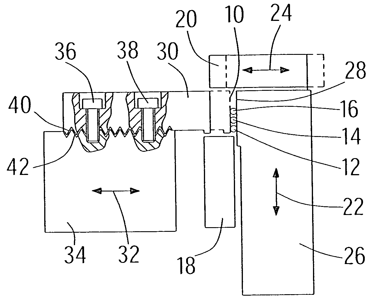
[0042]FIG. 1 depicts the limiting components of a compression chamber 10 of an ultrasonic welding device, in order to compact and weld long, extended, braid-like workpieces, such as conductors 12, 14, 16. In the diagram, the compression chamber 10 is delimited at the bottom by a working surface of a sonotrode 18. Opposite to sonotrode 18 is an anvil 20, which is raised and lowered (double arrow 22) so as to move parallel to the working surface of sonotrode 18 (double arrow 24). The anvil 20 proceeds thereby from a support 26, which, with a section 28, forms a right lateral limiting surface of the compression chamber 10. Opposite is an adjustably arranged slide valve 30 (double arrow 32), which proceeds from support 34. By adjusting the slide valve 30, support 34 respectively, the height of compression chamber 10 can be adjusted. According to the width of compression chamber 10, the working surface of anvil 20, which is opposite the working surface of sonotrode 18 is automatically ad...


PUM

PropertyMeasurementUnit
angleaaaaaaaaaa
angleaaaaaaaaaa
heightaaaaaaaaaa

Abstract

The invention concerns an ultrasonic welding device, which is more fully integrated by adjacent components of coupling surface. In order to permit a adequately fixed connection between the components, while, at the same time simplifying the mounting, it is suggested that at least some of the integrated components (30, 34) are structured in their coupling surfaces (40, 42), which lie on top of each another, for the achievement of a form closure.

Description

[0001]This application is a filing under 35 USC 371 of PCT / EP2004 / 007204 filed Jul. 2, 2004.BACKGROUND OF THE INVENTION[0002]The invention concerns a welding device, in particular an ultrasonic welding device, more fully integrated by adjacent components of coupling surfaces, such as a sonotrode and a booster, booster and converter, sonotrode and sonotrode head or carrying and working parts of a limiting, multipart anvil of a compression chamber. Further, the invention refers to a method for welding elongated, such as braid-like, workpieces via an ultrasonic device having a compression chamber containing workpieces, which is delimited by a sonotrode section, an opposite anvil section, and lateral limiting components, by which the width of the compression chamber is adjusted, whereby the workpieces are first placed in the compression chamber, near the enclosed, or partially compression chamber, enclosed by the anvil section, which is then focused on the total transverse area of the w...

Claims


Application Information

Patent Timeline
Patent Type & Authority Patents(United States)
IPC IPC(8): B23K1/06B23K20/10B23K37/00B23K5/20H01R43/02
CPCB23K20/106H01R43/0207B23K2201/38B23K2101/38B23K20/10H01R43/02
Inventor DIETERLE, HORSTWAGNER, PETER
Owner SCHUNK ULTRASCHALLTECHN
Why Eureka
Try Eureka