Local backup hydraulic actuator for aircraft control systems

a hydraulic actuator and local technology, applied in the direction of fluid couplings, couplings, transportation and packaging, etc., can solve the problems of reducing the reliability of each local hydraulic system comprising a motor, reducing the life of the motor and the pump, and being subject to being overworked and more likely to fail, so as to reduce the reliability and force fight, reduce the effect of reliability and reduced reliability

Active Publication Date: 2009-10-13
NABLESCO CORP
View PDF24 Cites 53 Cited by
  • Summary
  • Abstract
  • Description
  • Claims
  • Application Information

AI Technical Summary

Benefits of technology

[0015]By coupling the LBHAs to appropriate flight control surfaces, the airplane remains controllable with loss of all central hydraulic systems; therefore, the number of central hydraulic systems can be reduced compared to using only conventional hydraulic actuators.
[0021]A further advantage is that the backup system has a separate power source, namely electric power, so that increased availability of power is provided to the actuator. Because of this, providing one LBHA in conjunction with at least one hydraulic actuator for a particular surface is able to ensure that the likelihood of a complete loss of the power to position the surface correctly is negligible. This may, for example, enable reduction in the number of actuators coupled to a surface compared to only using conventional hydraulic actuators, while achieving an equivalent or better level of safety. This may also enable smaller, lighter, and simpler individual actuators than otherwise would have been possible.

Problems solved by technology

Flight control systems in commercial aircraft have redundancy to permit control of the aircraft in the event of failure of part of the system.
There are two major disadvantages associated with EHAs and the system comprising them.
One is the reduced reliability of each local hydraulic system comprising a motor, motor driver, and motor driver electronics.
They are subject to being overworked and are more likely to fail than a central hydraulic system or hydraulic actuator or such a central system.
Since they are required at each actuator, failure of one of these components will result in failure of the EHA.
In an active-active system, even minor differences in the timing of operation of the valves, pumps, and pressure in each system creates a force fight.
When dissimilar actuators, such as EHA and conventional hydraulic actuator, are used on a surface in an active-active fashion, blending them to work in perfect unison is very difficult, and so, a force fight is very likely to occur in this situation.
If there is a substantial force fight, the electric motor, pump, actuator components, or surrounding structure may be overloaded and subject to premature failure.
On the other hand, the force fight problem between dissimilar actuators on a particular surface used in an active-active fashion still remains.
Following the failure of the primary hydraulic source, however, the EBHA behaves as an EHA, and so, it is subject to the same aforementioned force fight issue associated with having an EHA and a hydraulic actuator on the same surface and having them work in an active-active fashion.
In addition, coupling only EBHAs to a surface and having them work in an active-active fashion would also result in the same situation when one of the primary hydraulic power sources fails.

Method used


Image

  • Local backup hydraulic actuator for aircraft control systems
  • Local backup hydraulic actuator for aircraft control systems
  • Local backup hydraulic actuator for aircraft control systems

Examples


Embodiment Construction

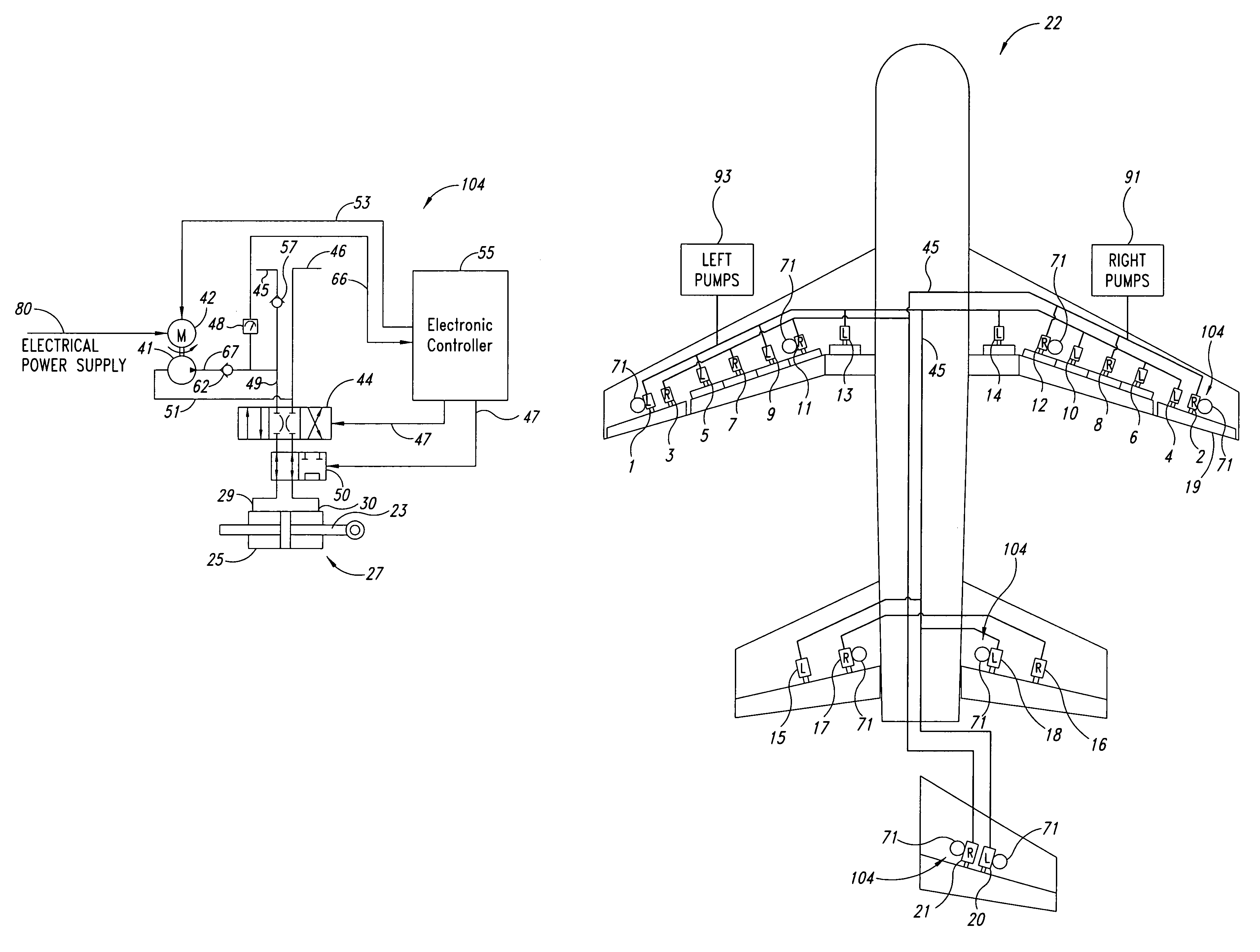
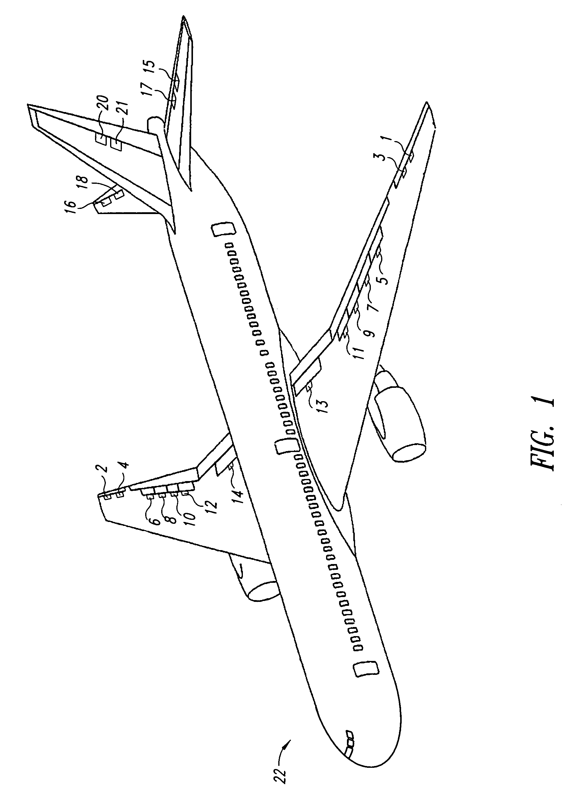
[0031]FIG. 1 shows an aircraft 22 having flight control surfaces controlled by a local backup hydraulic actuator according to the present invention. The aircraft 22 has a number of flight control surfaces. These include ailerons, spoilers, and, in some cases flaperons on each wing. Typically, these flight control surfaces provide roll, drag, lift, and load control. In addition, the aircraft 22 includes a rudder at a tail section and elevators, also at the empennage, to provide pitch and directional control of the aircraft.

[0032]Each of the flight control surfaces has connected thereto one or more hydraulic actuators for causing movement of the flight control surface according to principles of the present invention.

[0033]In the example shown, hydraulic actuators 1 and 3 control the aileron on the left wing, while hydraulic actuators 2 and 4 control the aileron on the right wing. Similarly, hydraulic actuators 5, 7, 1, 11, and 13 control the spoilers on the left wing. Similarly, hydra...


PUM


Abstract

A backup system is provided that has a local electric motor and pump for some or all of the hydraulic actuators on an aircraft. A local backup hydraulic actuator has two power sources, hydraulic as primary and electrical as backup. During normal operation, the hydraulic actuator receives pressurized fluid from a hydraulic system and the fluid flow to the chambers is controlled by a servo valve. If the hydraulic system fails, the electronic controller detects the failure by observing the signal indicative of the pressure from the pressure sensor, and the controller powers the local hydraulic pump to provide high pressure hydraulic fluid to the hydraulic actuator via the servo valve.

Description

BACKGROUND OF THE INVENTION[0001]This invention relates to aircraft flight control system and hydraulic system and, more particularly, to a method and apparatus for maintaining control of the aircraft if the primary hydraulic system is compromised.DESCRIPTION OF THE RELATED ART[0002]Flight control systems in commercial aircraft have redundancy to permit control of the aircraft in the event of failure of part of the system. For the hydraulic actuators that control the flight control surfaces, backup systems are present on each aircraft so that if one of the hydraulic systems fails, other systems are available to provide power to control sufficient flight control surfaces.[0003]A commercial aircraft typically has a plurality of independent central hydraulic systems, usually two or three, depending on the type of aircraft. The hydraulic pressure in each central hydraulic system is generated by one or more centrally located hydraulic pumps which are driven directly or indirectly by a ma...

Claims


Application Information

Patent Timeline
Patent Type & Authority Patents(United States)
IPC IPC(8): B64C13/00
CPCB64C13/42F15B20/004B64C2013/506Y02T50/44B64C13/504B64C13/505Y02T50/40
Inventor MATSUI, GEN
Owner NABLESCO CORP
Why Eureka
Try Eureka