
Clip-on or snap-on fastening for fixing a thin wall to a wall support

a technology of snap-on and wall support, which is applied in the direction of carpet fasteners, sheet joining, dwelling equipment, etc., can solve the problems of poor strength of the holder, poor stability of the holder, and inability to ensure the integrity of the holder

Active Publication Date: 2009-10-13
RAMSAUER DIETER
View PDF33 Cites 12 Cited by
  • Summary
  • Abstract
  • Description
  • Claims
  • Application Information

AI Technical Summary

Benefits of technology

[0005]It is the primary object of the invention to provide a snap fastening of the type mentioned above which overcomes these disadvantages and ensures excellent springiness over an unlimited period of time and in which the design, due to its simplicity, enables inexpensive production and a simple assembly makes it possible to produce, e.g., sheet metal cabinets and all types of casings, coverings and end closures less expensively.

Problems solved by technology

It is disadvantageous that the plastic material can lose its integrity and springiness over the course of time and with frequent stress and that the strength of the holder is not ensured.
Further, the construction is very complicated and expensive.

Method used


Image

  • Clip-on or snap-on fastening for fixing a thin wall to a wall support
  • Clip-on or snap-on fastening for fixing a thin wall to a wall support
  • Clip-on or snap-on fastening for fixing a thin wall to a wall support

Examples


Embodiment Construction

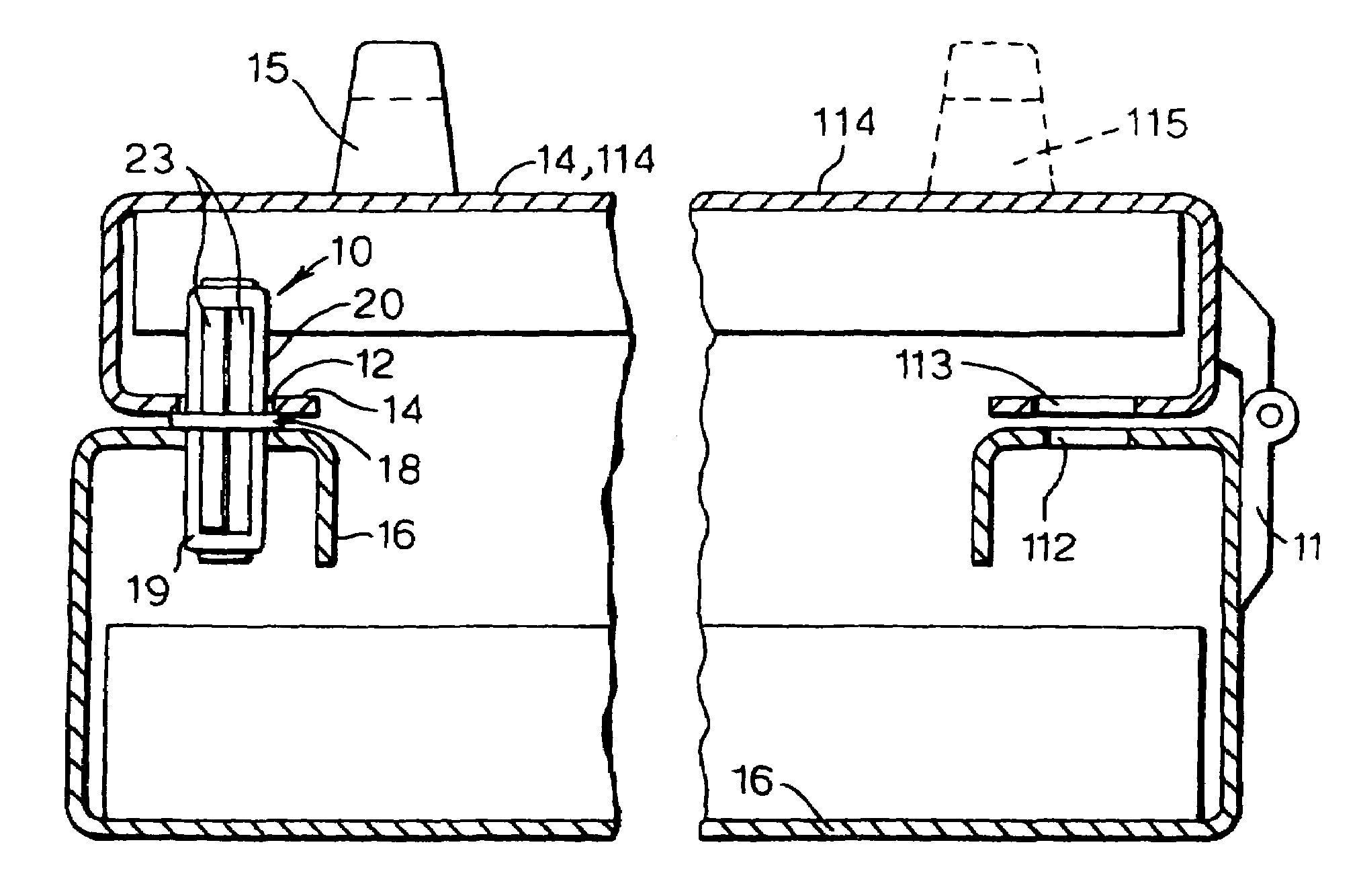
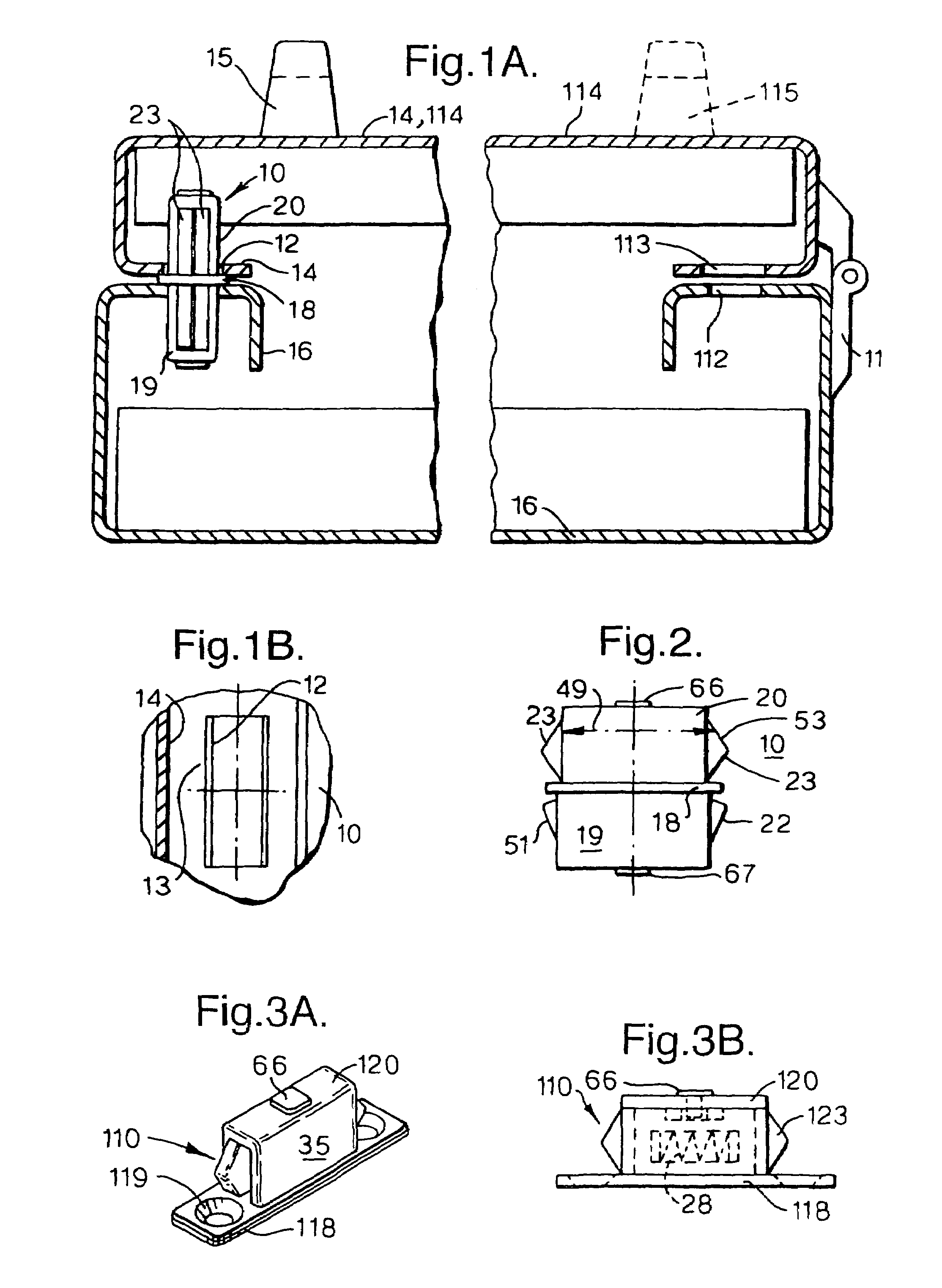
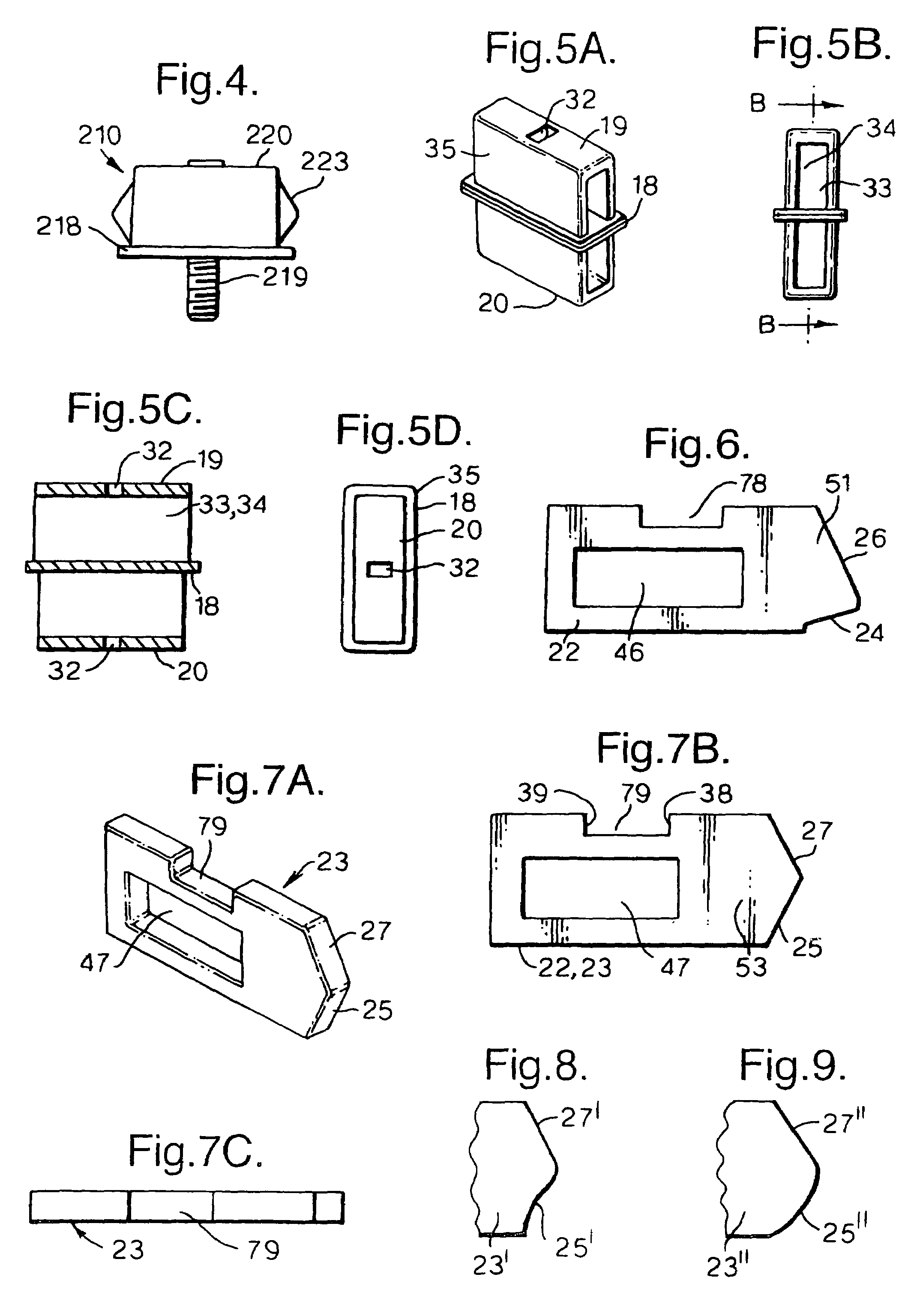
[0128]FIG. 1A is a cross-sectional view showing a snap fastening 10 for fixing a thin wall 14, such as a housing wall, in this case a door leaf 14, shutter, or the like, which is provided with an opening 12, to a wall support 16 such as a housing frame, door frame, wall opening edge, or the like, which is likewise provided with an opening 12, having a base part 18 that can be arranged at the wall support 16 in the opening 12, with a head part 20 which extends away from this base part 18 and which has in its longitudinal section, shown as a side view in FIG. 2, a diameter that first increases and then decreases again from the end of the head part 20 in direction of the base part 18, which head part 20 is a male plug-in part which, by overcoming a spring force (see spring 28 in FIG. 3B) acting radially in direction of the longitudinal section, can be received by an undercut plug-in part that is formed or carried by the opening 13 in the thin wall 14. The head part 20 of the snap faste...


PUM


Abstract

The description relates to a snap fastening for fixing a thin wall, such as a housing wall, door leaf, or shutter, which is provided with an opening, to a wall support such as a housing frame, door frame, or wall opening edge, which is likewise provided with an opening, with a base part that can be arranged at the wall support in its opening, with a head part which extends away from this base part and which has a diameter that initially increases and then decreases again in its longitudinal section from the end of the head part in direction of the base part, which head part is a male plug-in part which, by overcoming a spring force acting radially outward in direction of the diameter, can be received by an undercut female plug-in part that is formed or carried by the opening of the thin wall.

Description

CROSS-REFERENCE TO RELATED APPLICATIONS[0001]This application claims priority of International Application No. PCT / EP2005 / 002084, filed Feb. 28, 2005 and German Application No. 20 2004 003 238.4, filed Feb. 27, 2004, German Application No. 20 2004 005 083.8, filed Mar. 29, 2004 and German Application No. 20 2004 016 009.9, filed Oct. 15, 2004, the complete disclosures of which are hereby incorporated by reference.BACKGROUND OF THE INVENTION[0002]The invention is directed to a snap fastening for fixing a thin wall, such as a housing wall, door leaf, shutter, or the like, which is provided with an opening, to a wall support such as a housing frame, door frame, wall opening edge, or the like, with a base part that can be arranged at the wall support in the opening, with a head part which extends away from this base part and which has a diameter that first increases and then decreases again in its longitudinal section from the end of the head in direction of the base part, and which hea...

Claims


Application Information

Patent Timeline
Patent Type & Authority Patents(United States)
IPC IPC(8): E05C1/08E05C1/00E05C1/16E05C19/02F16B5/06
CPCE05C1/16E05C19/028Y10S292/04Y10S292/54Y10S292/68Y10S292/53Y10S292/38Y10T292/0969Y10T292/14Y10T292/097Y10T292/0834Y10T292/084Y10T70/5558F16B5/06
Inventor RAMSAUER, DIETER
Owner RAMSAUER DIETER
Learn More