Device to transfer catalyst from a low pressure vessel to a high pressure vessel and purge the transferred catalyst

a technology of catalyst and high pressure vessel, which is applied in the direction of transportation and packaging, bulk conveyors, chemistry apparatus and processes, etc., can solve the problems of catalyst loss and add to maintenance, and achieve the effect of saving time and money and improving operation

Active Publication Date: 2009-10-13
UOP LLC
View PDF18 Cites 10 Cited by
  • Summary
  • Abstract
  • Description
  • Claims
  • Application Information

AI Technical Summary

Benefits of technology

[0005]A solution for the problem of transferring solid particles from a low pressure vessel to a high pressure vessel can improve operation and save time and money. The present invention provides for a smaller, simpler and less expensive apparatus for transferring solid catalyst from a low pressure vessel to a high pressure vessel and to control the flow rate without the need of a nuclear level instrument. The apparatus comprises a flow control vessel situated between the low pressure vessel and the high pressure vessel and is in fluids communication with the low pressure vessel and the high pressure vessel through a solids transfer line. The flow control vessel is smaller than either the low pressure vessel or the high pressure vessel. The apparatus includes the flow control vessel for collecting transferred particles for subsequent feed to the high pressure vessel. Situated between each of the vessels are solid particle transfer valves for controlling the flow of solids through the apparatus, and for controlling the pressure levels in the flow control vessel. The apparatus further comprises a high pressure inert gas source for supplying inert gas to the flow control vessel at a pressure at least as great as the pressure in the high pressure vessel. The high pressure inert gas in controlled through a valve to regulate the pressure in the flow control vessel and in the intermediate section of the solids transfer line.

Problems solved by technology

Problems exist for the first two systems which add to maintenance and the loss of catalyst through grinding that creates fines, especially in the gas tight valves where the valves are completely closed in the solid and gas lines in the dusty environment and which eventually develop leaks.

Method used


Image

  • Device to transfer catalyst from a low pressure vessel to a high pressure vessel and purge the transferred catalyst
  • Device to transfer catalyst from a low pressure vessel to a high pressure vessel and purge the transferred catalyst

Examples


Embodiment Construction

[0008]There are many processes that involve the transfer of solids between vessels. While many processes allow for the transfer through fluidization, or the use of positive pressure differentials, often there are processes where the vessels containing the solids are operated at different conditions. A particular problem exists when the solids, usually in particulate form, need to be transferred from a lower pressure vessel to a higher pressure vessel. To avoid the need for extra vessels for the transfer of solids, or for large complex vessels having segregated internal chambers, it has been found that a single smaller vessel can handle the transfer. An important process that passes solid catalyst from a low pressure system to a high pressure system involves moving bed systems where solid catalyst particles cycle between a reactor bed and a regenerator.

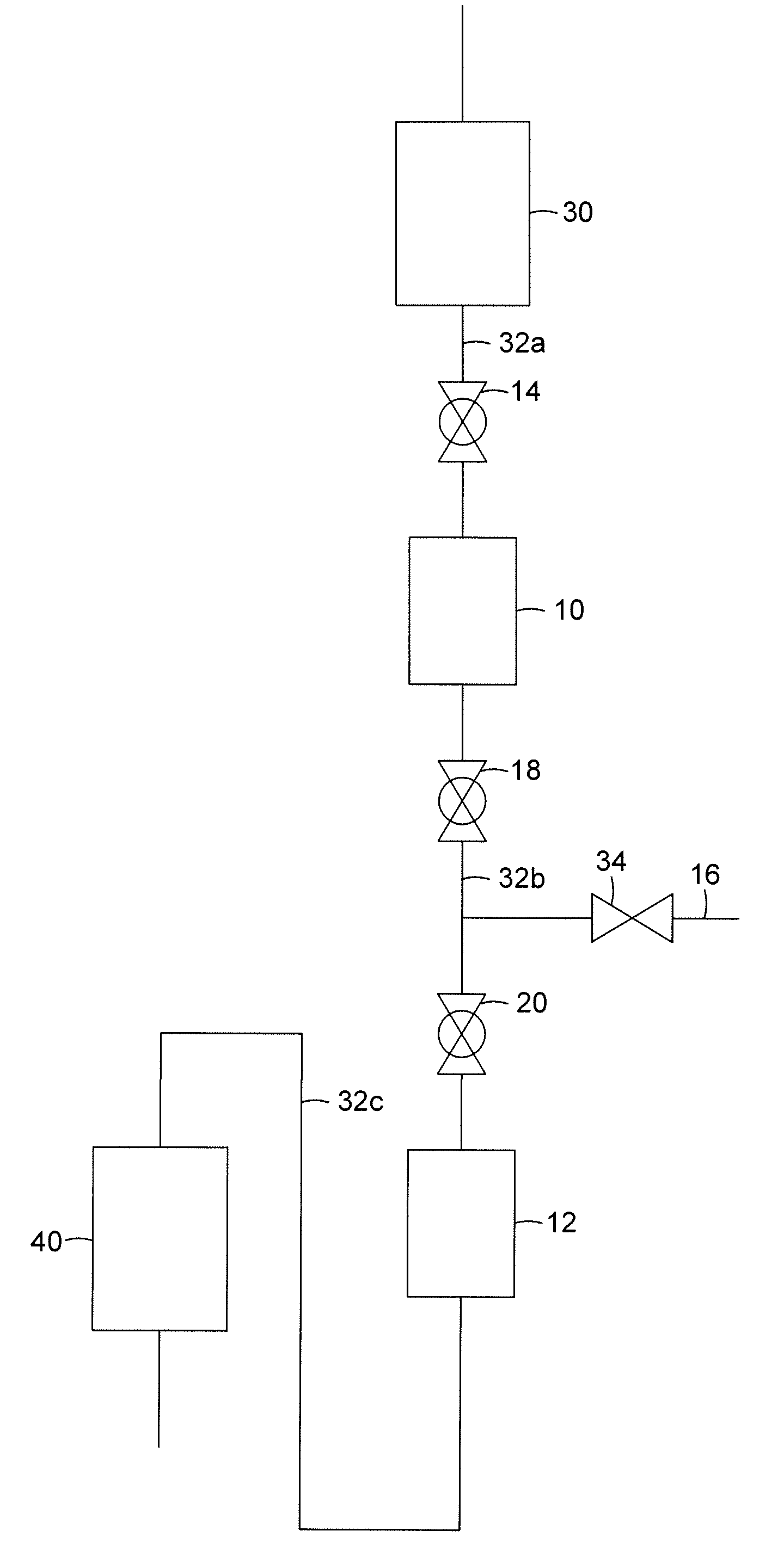
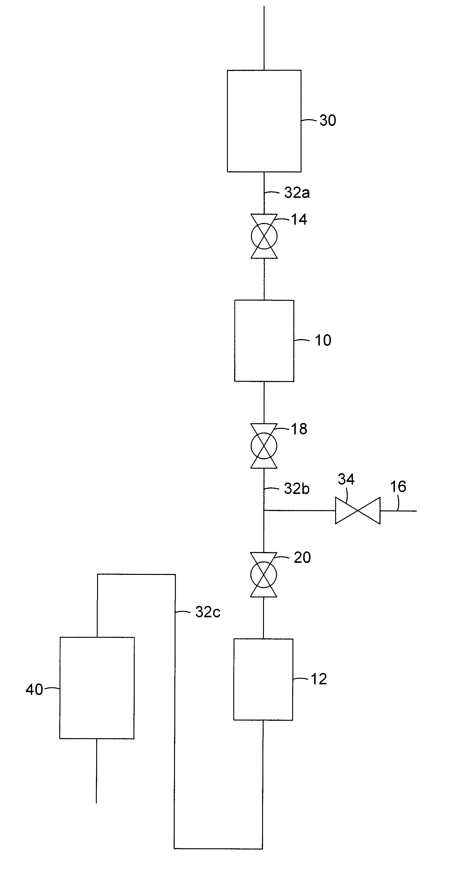
[0009]The present invention, as illustrated in the FIGURE, comprises a flow control vessel 10, a surge hopper 12, a first solid parti...


PUM


Abstract

An apparatus for the transfer of solid particulate matter from a low pressure system to a high pressure system is presented. The apparatus simplifies the particle transfer process, and is useful for systems where solid catalyst particles are cycled through a reactor and a regenerator.

Description

BACKGROUND OF THE INVENTION[0001]This invention relates to the handling of solid materials, and particularly the handling of solid particulate materials where they are passed from a low pressure system to a higher pressure system. There are many processes in the petrochemical industry that use catalysts and adsorbents. The catalysts and adsorbents are frequently transferred between reaction units and regeneration units, and often there is a flow of the catalyst and / or adsorbent through the system comprising the reaction unit and the regeneration unit.[0002]Currently, the transfer of catalyst between two vessels with reverse pressure gradient is achieved by using a valved lock hopper and flow control hopper, by valved lock hopper with a nuclear level detection instrument or by using a valveless hopper. The flow control and valved lock hopper is used to change the pressure and environment, in order to transfer the solid material from a lower pressure vessel to a higher pressure vessel...

Claims


Application Information

Patent Timeline
Patent Type & Authority Patents(United States)
IPC IPC(8): B65G53/36
CPCB01J8/0015B65G53/06B01J2208/00548B01J2208/00539
Inventor YUAN, LEON
Owner UOP LLC
Why Eureka
Try Eureka