Fused sensor situation display

a sensor and situation display technology, applied in the field of command and control displays, can solve the problems of difficult communication and often lost activity outside the immediate area of interest to the observer

Inactive Publication Date: 2009-10-13
LOCKHEED MARTIN CORP
View PDF3 Cites 5 Cited by
  • Summary
  • Abstract
  • Description
  • Claims
  • Application Information

AI Technical Summary

Benefits of technology

[0008]The present invention enables an operator and / or observer to gain an intuitive and rapid understanding of the tactical situation surrounding a tactical platform or point-of-interest, such as a warship, aircraft, fixed installation, or motor vehicle. For example, embodiments of the present invention are particularly well-suited for providing an operator / observer to command and control defense assets in the face of an attack by a large number of fast attack craft, such as fast gun boats.
[0009]In conventional prior art C2 systems, on-board and off-board sensing systems typically transmit sensor information to the defended platform over separate communications links. This sensor information is displayed on separate tactical displays, each of which displays information from only a single sensing system. As a result, overall sensing information is distributed over several displays, which are often physically displaced from each other. This plurality of screens is typically monitored by multiple operators / observers. Since these observers receive sensor information in piecemeal fashion, communications between them is necessary to develop a composite sense of the surrounding environment. Such communication can be difficult in the often chaotic, confused, and noisy environment of a battle, however. Mistakes, such as firing a weapon at a neutral or friendly contact, therefore, can easily be made.
[0012]In some embodiments of the present invention, a display provides information from sensors that sense energy from other areas in the electromagnetic spectrum. This integrated view can be displayed in a single display area observable by a single observer or groups of observers. The observers, therefore, are able to quickly develop an intuitive awareness of the tactical situation that surrounds the warship and can thereby assign additional sensors and / or weapons necessary to counter an attack. In some embodiments, the tactical status of both the attackers and the ship's sensor and weapon resources being assigned to counter the attackers are also displayed in the integrated view.
[0014]In some embodiments, instantaneous fields of regard (magnification) of select sensors, such as high resolution EO and IR sensors, are rendered in the display to help orient the users of those higher resolution displays and to further augment tactical awareness. In some embodiments, the pointing angle and field of regard of high resolution sensors are graphically controlled using an operator controlled cursor on a display. In some embodiments, the cursor is used to move or resize the displayed field of regard of a sensor which in turn slews the physical sensor and / or changes the sensor's magnification. This enables an operator to control several high resolution sensors at one time.
[0016]The present invention, therefore, enables a single observer to rapidly obtain an intuitive awareness of a more complete tactical situation surrounding the ship. The speed at which command and control decisions can be made is thereby improved as compared to conventional prior art tactical displays. In addition, the present invention can obviate the need for inter-personnel communication that can also contribute to command errors.

Problems solved by technology

Such communication can be difficult in the often chaotic, confused, and noisy environment of a battle, however.
As a result, activity outside the immediate area of interest is often lost to the observer.

Method used


Image

  • Fused sensor situation display
  • Fused sensor situation display
  • Fused sensor situation display

Examples


Embodiment Construction

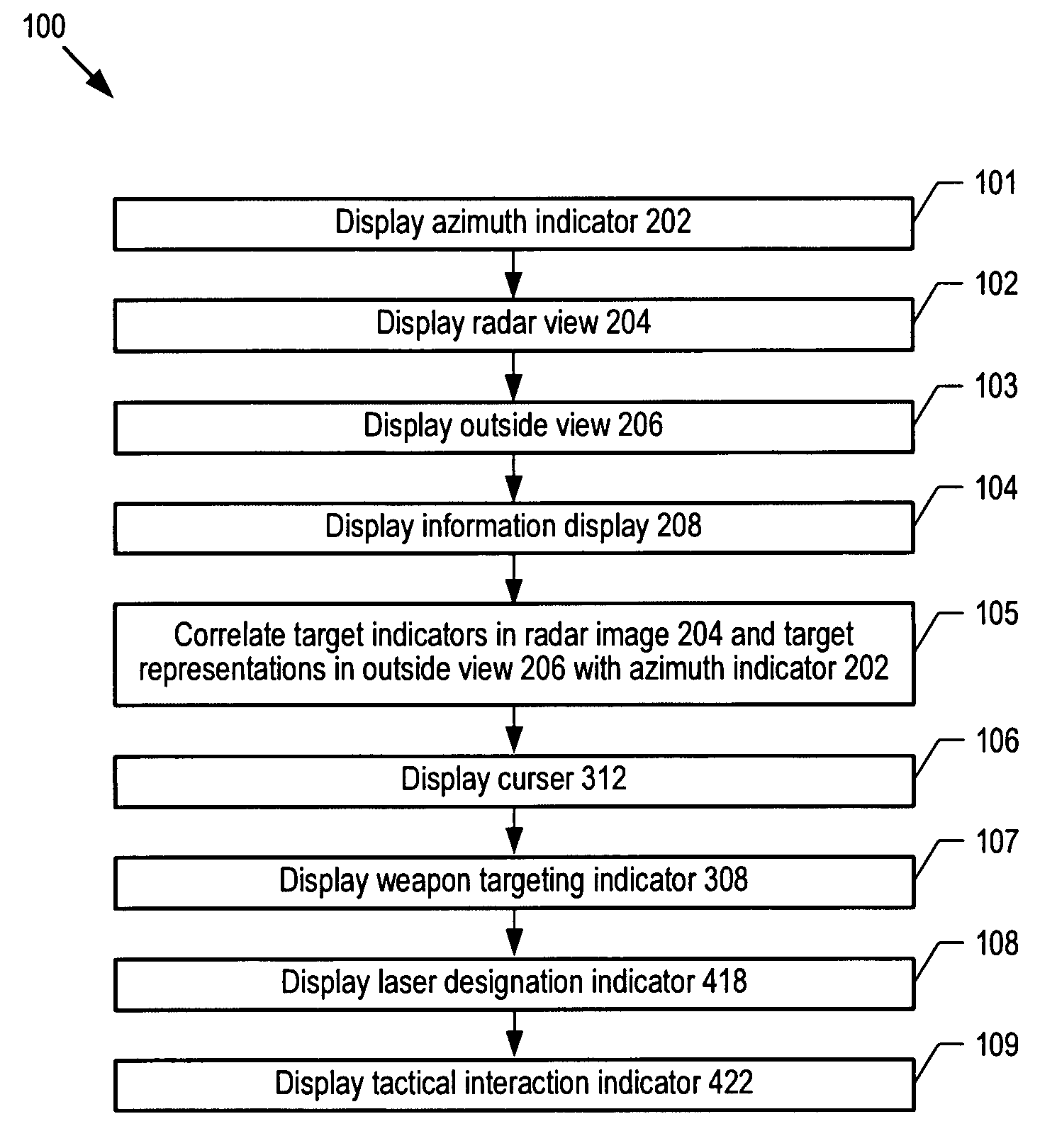
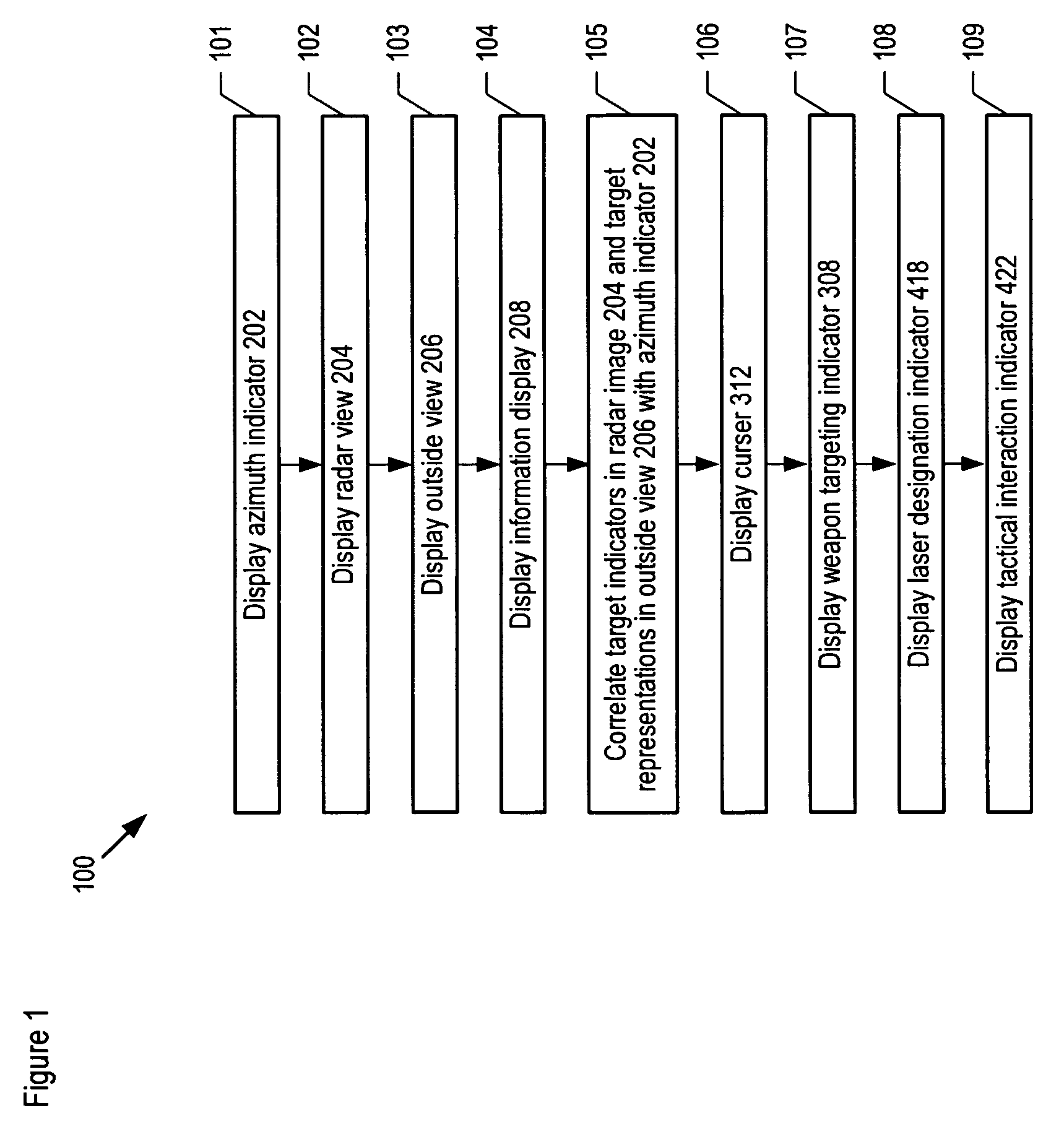
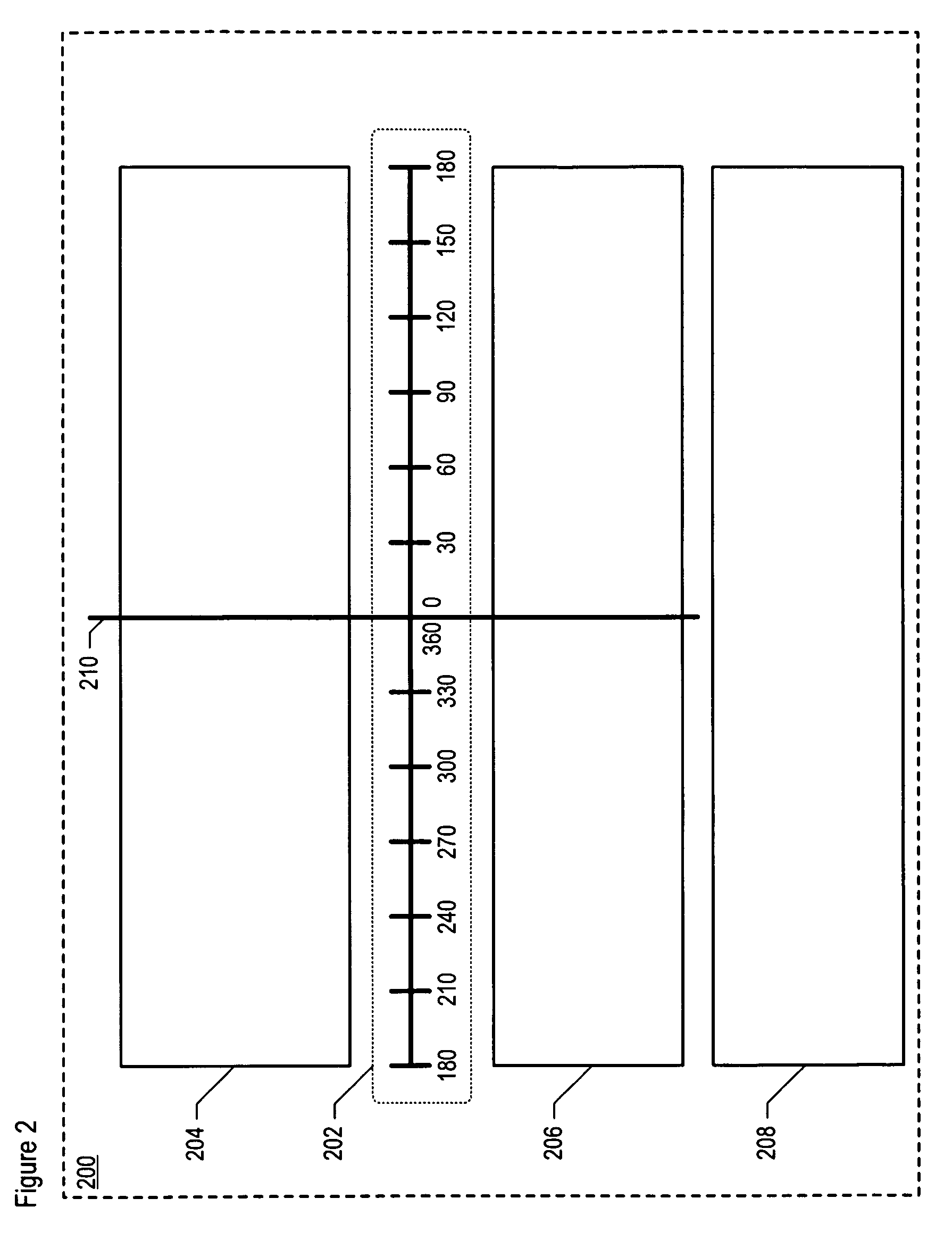
[0023]The following terms are defined for use in this Specification, including the appended claims:[0024]azimuth means the horizontal component of a direction, measured clockwise around the horizon, from a reference direction.[0025]radar image means a rendering of information provided by radar equipment. Such information may include range and azimuth information for: (1) substantially stationary contacts, such as land masses, weather formations, military installations, civilian installations, and the like; and (2) non-stationary contacts, such as aircraft, ships, motor vehicles, personnel, and the like.[0026]radar data means location, direction, speed, and / or track of a contact or each of a set of contacts.[0027]tactical information means information about a contact. Tactical information includes one or more of the following: a contact's track history, a contact's threat level, a contact's weaponry, historical group-related activity of a contact, historical information for a contact...


PUM


Abstract

A method for providing an observer with an intuitive awareness of a tactical environment is disclosed. In an illustrative embodiment, the method displays a 360° panoramic view of the environment surrounding a warship, wherein the view is augmented by radar data, infrared imagery, visible imagery, and tactical information about targets within the field-of-view.

Description

FIELD OF THE INVENTION[0001]The present invention relates to command and control displays in general, and, more particularly, to radar displays, electro-optical sensor displays and infrared sensor displays.BACKGROUND OF THE INVENTION[0002]In modern warfare, command and control (C2) systems are found in warships, aircraft, tanks, and other land vehicles. These C2 systems are used for, among other things, the deployment of friendly assets and control of sensors and weaponry during military operations. A typical C2 system includes processing elements, communications elements, and control elements that use a variety of displays to provide information about a tactical environment to several observers. Each observer may monitor one aspect (or a few aspects) of the overall tactical situation and communicate about that aspect to the other observers, thereby cooperatively developing “community” awareness that leads to a tactical decision.[0003]In a large set-piece military operation, such as...

Claims


Application Information

Patent Timeline
Patent Type & Authority Patents(United States)
IPC IPC(8): G01C3/08
CPCF41G3/04F41G3/165F41G9/00G01S13/867G01S7/062G01S7/22G01S7/06F41G3/02
Inventor ROOT, JR., GEORGE RAYMOND
Owner LOCKHEED MARTIN CORP
Why Eureka
Try Eureka