Optical window contamination detecting device for optical apparatus

a technology of optical equipment and detection device, which is applied in the direction of distance measurement, instruments, and using reradiation, etc., can solve the problems of high cost of the device, inability to appropriately display the distance measurement function, and the requirement of transmitting/receiving elements

Active Publication Date: 2009-10-13
HOKUYO AUTOMATIC CO
View PDF16 Cites 17 Cited by
  • Summary
  • Abstract
  • Description
  • Claims
  • Application Information

AI Technical Summary

Problems solved by technology

However, when the optical window 102 becomes contaminated with mud, water droplets, or the like, there arises a serious problem that the distance measuring function cannot be appropriately exhibited, such as an appropriate amount of light is not irradiated, and the light reflected by the object X is not detected.
However, in the technique described in the U.S. Pat. No. 5,455,669, there arise new problems such as adjustment of an optical axis of each light transmitting / receiving element and prevention of interference between the light transmitting / receiving elements arranged side by side, since a great number of light transmitting / receiving elements must be arranged side by side at small intervals to detect the entire region of the optical window without any blind spots when it is necessary to detect minor contamination.
Furthermore, the number of components increases and thus the device becomes expensive.
In the technique described in Japanese Laid-Open Patent Publication No. 10-90412, the device can be configured more compact than that described in Patent Publication No. 5,455,669, but has a problem in that, when water droplets attach to a reflecting surface of a case, judgment is sometimes mistakenly made if the light is reflected diffusely by the water droplets and detected by the measurement light receiving element, and also has another problem in that a great number of light transmitting / receiving elements are required similarly to the above-described case when it is necessary to detect minor contamination on the optical window.

Method used


Image

  • Optical window contamination detecting device for optical apparatus
  • Optical window contamination detecting device for optical apparatus
  • Optical window contamination detecting device for optical apparatus

Examples


Embodiment Construction

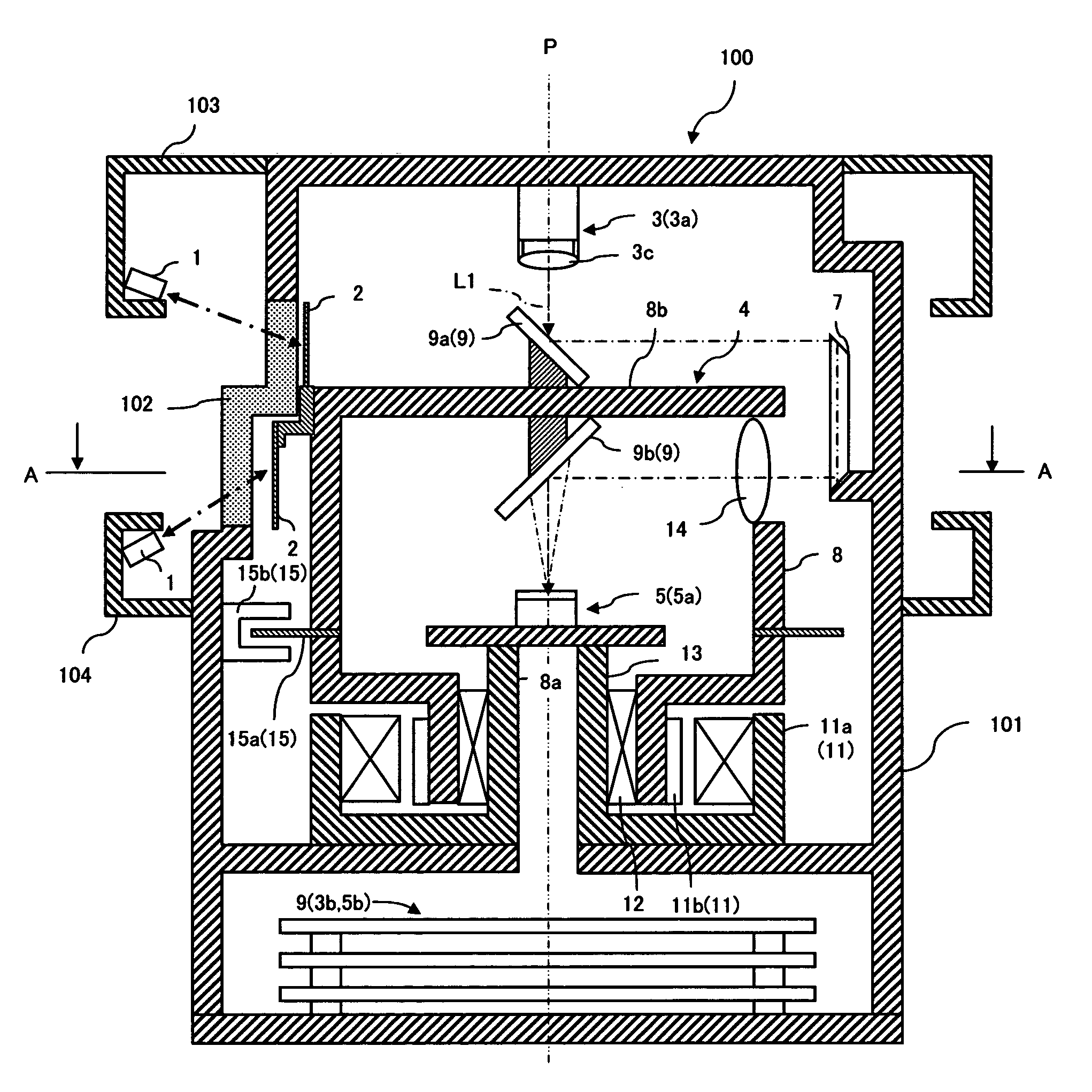
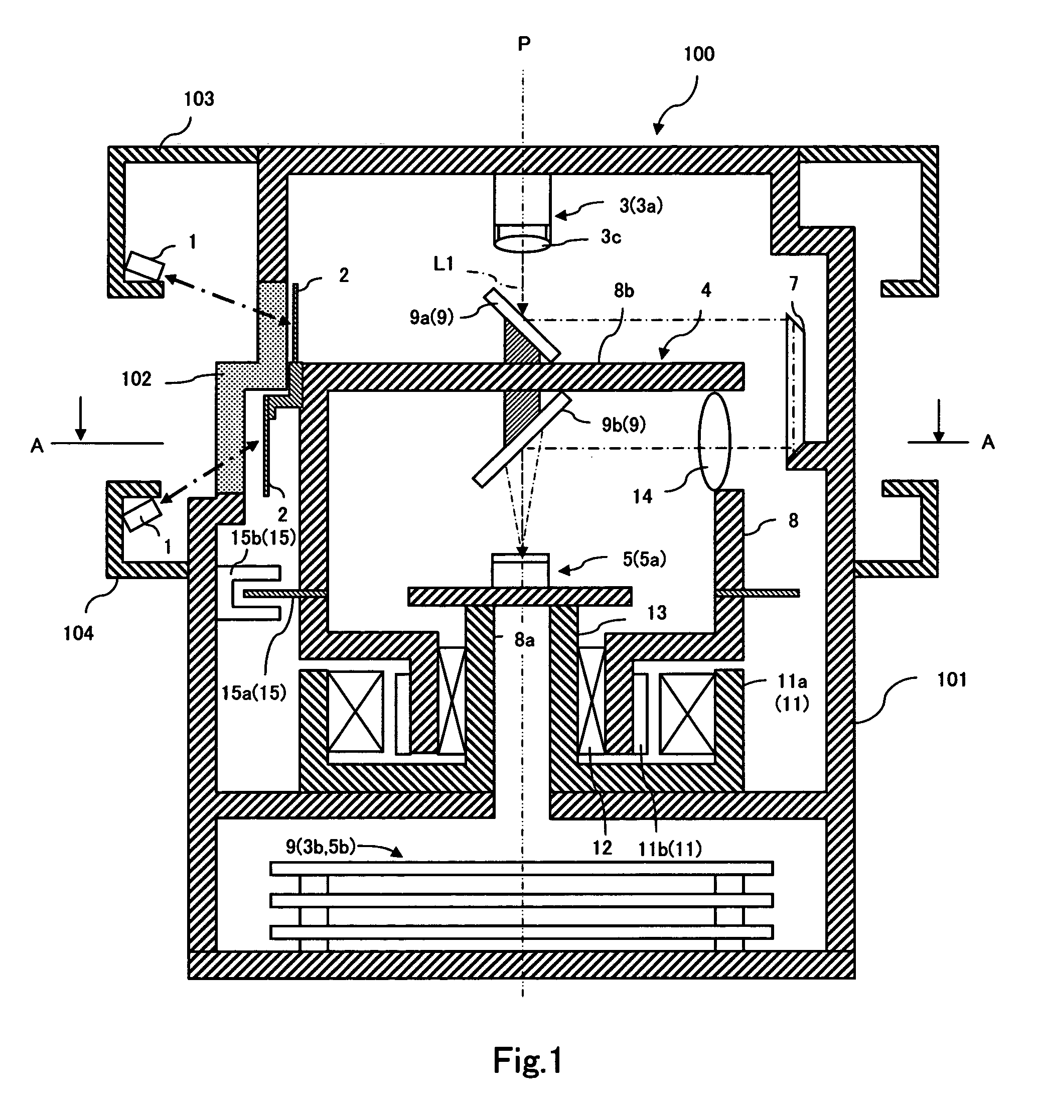
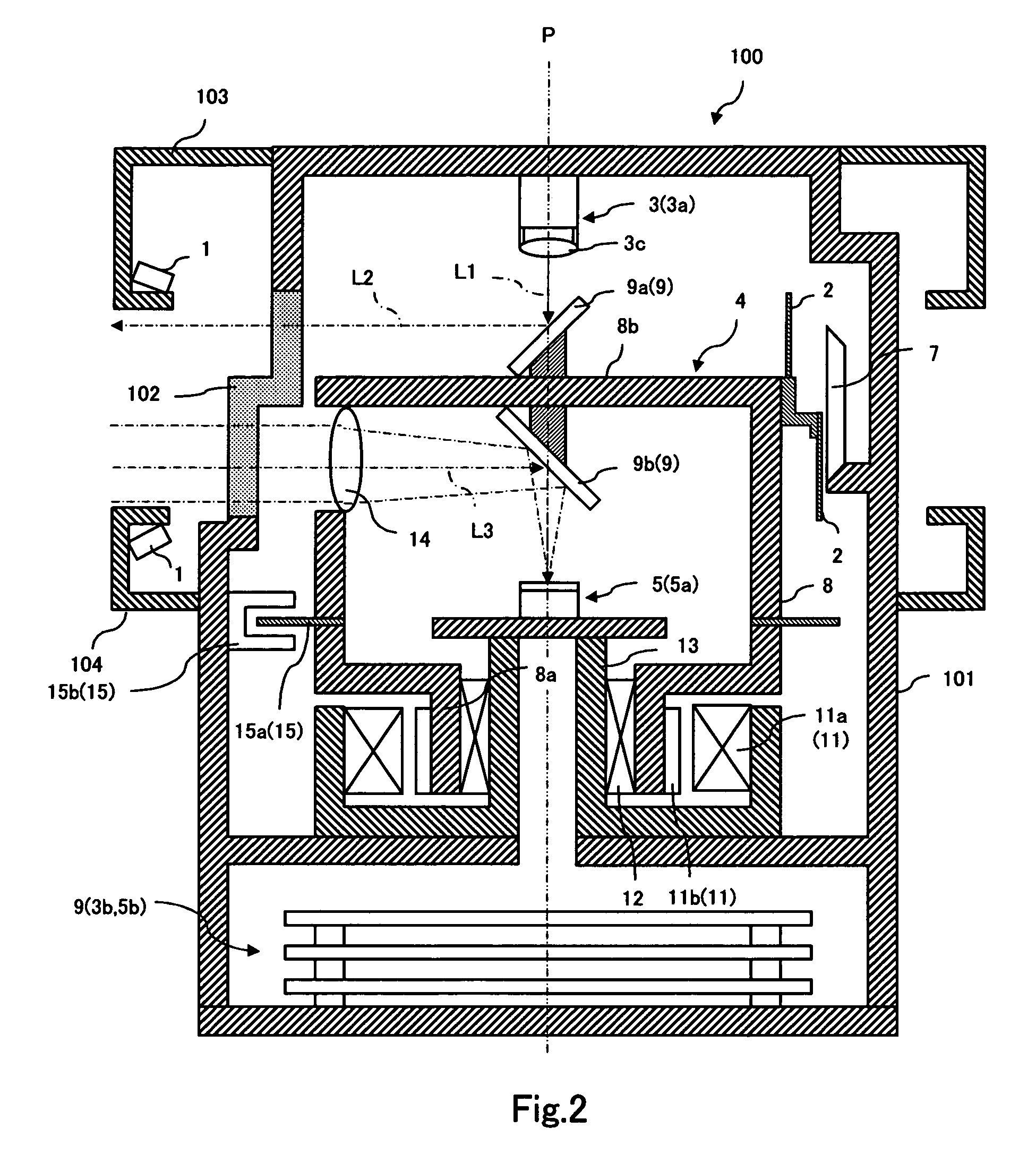
[0028]The following is a description of an example in which an optical window contamination detecting device according to the present invention is applied to an optical window of a scanning type distance measuring apparatus.

[0029]Generally, the distance measuring apparatus applies modulation to measurement light output from a laser light source LD, irradiates the light to an object X through an optical window 102, and measures a distance by detecting reflected light from the object X with a light receiving element PD through the optical window 102, as shown in FIG. 8, where two types of AM (Amplitude Modulation) method and a TOF (Time of Flight) method are put into practical use as methods for modulating the measurement light.

[0030]The AM method is a method of photoelectrically converting measurement light AM modulated at a sine wave and reflected light thereof, calculating a phase difference Δφ between signals thereof, and computing a distance from the phase difference Δφ, as shown...


PUM

PropertyMeasurementUnit
angle of inclinationaaaaaaaaaa
reflectivityaaaaaaaaaa
angle detectingaaaaaaaaaa

Abstract

An optical window contamination detecting device capable of detecting even microscopic contamination on an optical window with a limited number of contamination detecting sensors. The optical window contamination detecting device is used for a scanning type distance measuring apparatus that includes a casing, formed with an optical window, which accommodates a light transmitting unit, a scanning mechanism for deflection scanning measurement light output from the light transmitting unit into a measuring space through the optical window, and a light receiving unit for detecting reflected light from an object through the optical window. The optical window contamination detecting device includes a plurality of reflection photoelectric sensors arranged along the optical window on an outer side of the optical window and a retro-reflective member attached to the scanning mechanism, the retro-reflective member for reflecting detection light from the reflection photoelectric sensor having passed through the optical window towards the reflection photoelectric sensor.

Description

[0001]This application is based on an application No. 2006-355154 filed in Japan, the contents of which are hereby incorporated by reference.BACKGROUND OF THE INVENTION[0002]1. Field of the Invention[0003]The present invention relates to an optical window contamination detecting device for an optical apparatus such as an imaging apparatus for deflection scanning light with a mirror, irradiating with the light a measuring space outside the apparatus to acquire a one-dimensional image from an intensity of reflected light from an object, and a light wave distance measuring apparatus for measuring a distance based on delay time between modulated measurement light and reflected light from an object.[0004]2. Description of the Related Art[0005]As shown in FIG. 8, there is proposed a scanning type distance measuring apparatus 100 accommodating, in a casing 101 formed with an optical window 102, a light transmitting unit 3, a scanning mechanism 4 for deflection scanning measurement light ou...

Claims


Application Information

Patent Timeline
Patent Type & Authority Patents(United States)
IPC IPC(8): G01N21/00G01N21/55G01N21/94G01S17/931G01V8/20
CPCG01S7/481G01S7/4812G01S7/4817G01S17/42G01S17/936G01S7/497G01S2007/4975G01S17/931
Inventor MORI, TOSHIHIRO
Owner HOKUYO AUTOMATIC CO
Why Eureka
Try Eureka