Piezoelectric sensor

a technology of piezoelectric sensor and piezoelectric motor, which is applied in the direction of fluid pressure measurement, generator/motor, instruments, etc., can solve the problems of increasing manufacturing handling difficulties, complicated handling of individual measuring elements, and small structures, and achieves the effect of further simplifying the positioning of measuring elements

Inactive Publication Date: 2009-10-20
PIEZOCRYST ADVANCED SENSORICS
View PDF8 Cites 21 Cited by
  • Summary
  • Abstract
  • Description
  • Claims
  • Application Information

AI Technical Summary

Benefits of technology

[0009]It is the object of the present invention to improve a piezo-electric sensor, for instance a pressure sensor, with a plurality of piezoelectric measuring elements in such a way that positioning of the measuring elements will be further simplified while sufficient electrical insulation of the measuring elements from the interior wall of the housing—especially at high temperatures—will be ensured.
[0010]This object will be achieved by the invention by providing that the piezoelectric measuring elements are attached to the pick-up electrode by thermo-compression or soldering, thus forming a compact stack together with the pick-up electrode. Attaching the individual measuring elements to the pick-up electrode can be carried out externally of the sensor or the sensor housing, and thus slipping or sliding of the measuring elements during assembly of the sensor will be avoided. In the completed sensor movement between the measuring elements and the contact face of the electrode due to differing thermal expansion coefficients will still be possible, since at higher temperatures the ductile layers or the solder between measuring elements and pick-up electrodes will soften and will thus permit a slight sliding motion between measuring elements and the contact points.
[0011]In a first variant of the invention the piezoelectric measuring elements are preferably lamella-shaped, and are attached to the pick-up electrode with the narrow side by thermo-compression or soldering to make use of the transversal piezoeffect. To enhance movability at high temperature loads the stacked piezoelectric measuring elements can be provided with an air gap between adjacent side faces.

Problems solved by technology

This makes handling, in particular positioning and aligning, of the individual measuring elements rather complicated.
In the instance of certain pressure sensors which are inserted in indicator bores, the sensor housing has an interior diameter of about 2 mm only, leading to very small structures and thus to increased handling difficulties in manufacturing.
A further disadvantage inherent in the use of plastic positioning means is due to their increasing conductivity at high temperatures, which may cause the sensor to fail.
), leading to a substantial increase in conductivity and thus to electrical short circuits.
Both the simple crystal with its base and the double crystal with a divided base made up of two mirror halves, are relatively complicated to manufacture, and the remaining handling effort for assembling the sensor is still considerable.
Glueing, as described in document GB 2 022 261 A, has further disadvantages, since at higher temperatures the insulation properties will deteriorate due to evaporating residual glue.

Method used


Image

  • Piezoelectric sensor
  • Piezoelectric sensor
  • Piezoelectric sensor

Examples


Embodiment Construction

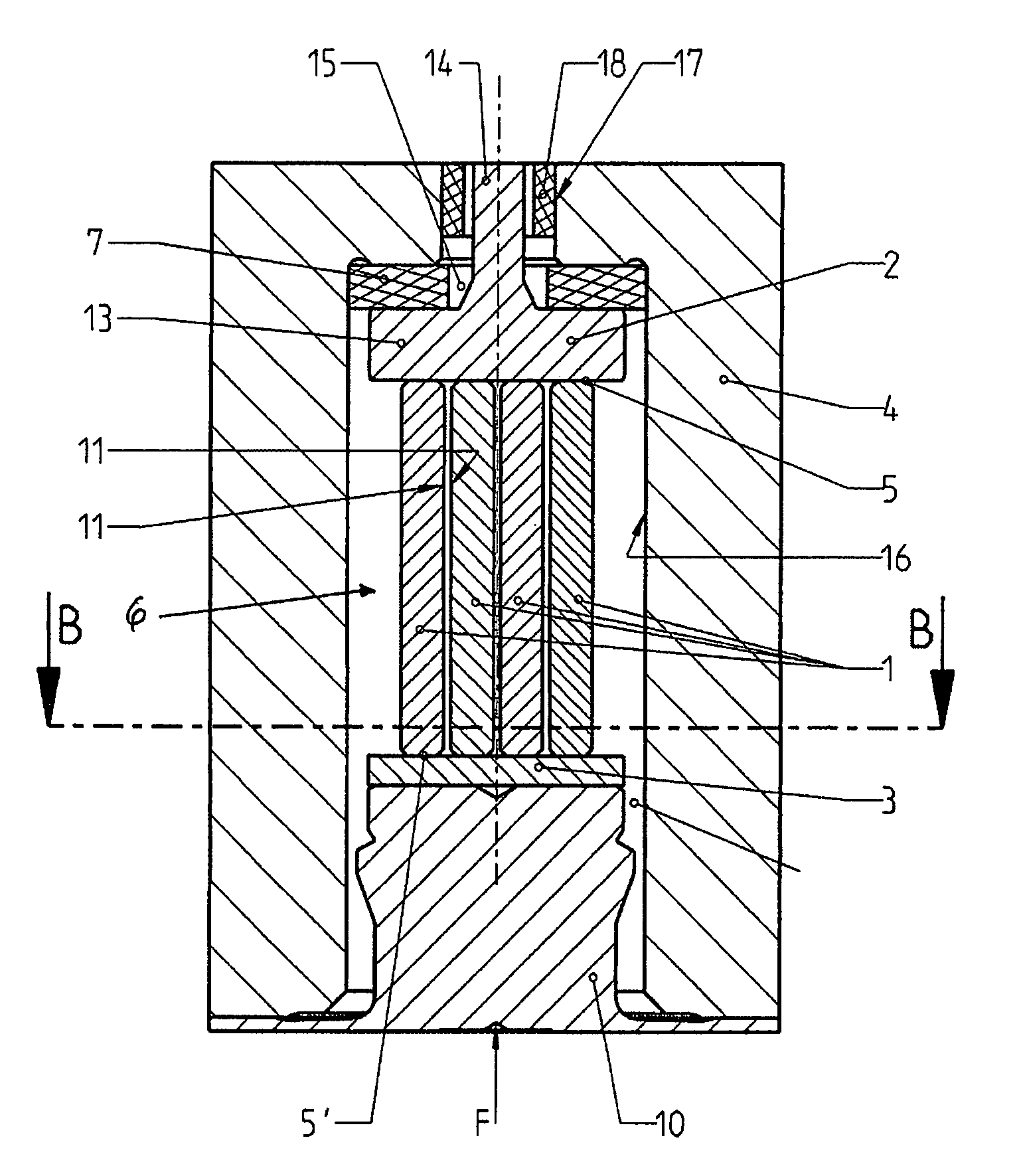
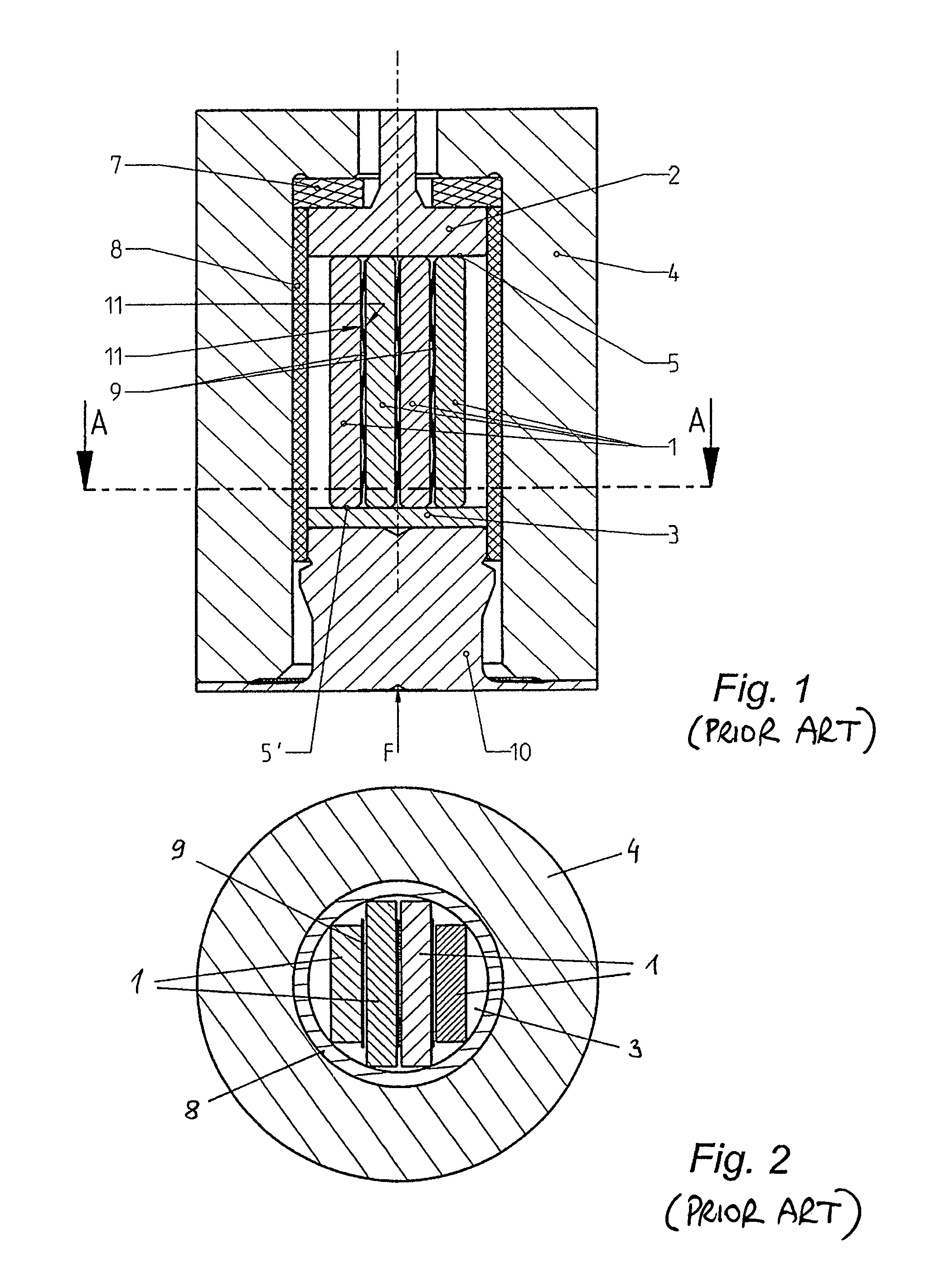
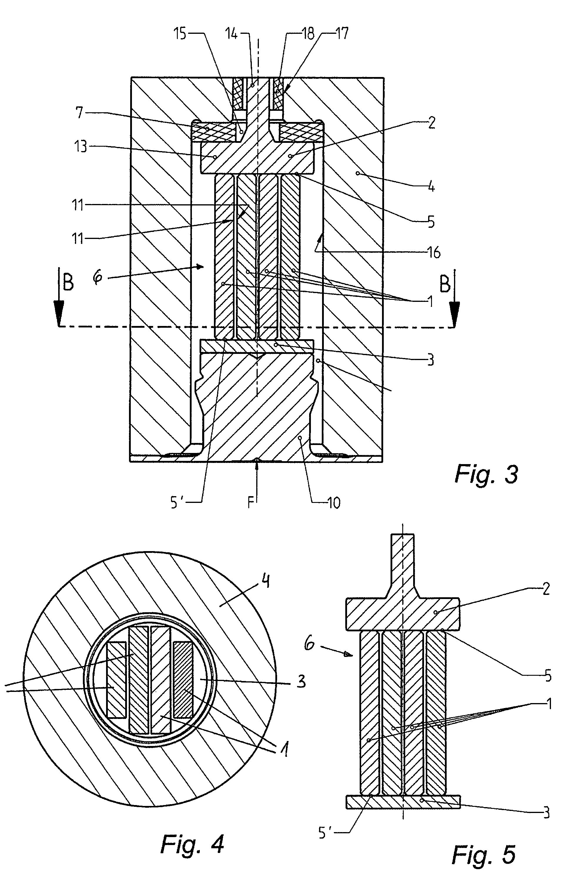
[0026]The state-of-the-art piezoelectric pressure sensor shown in FIGS. 1 and 2 has four lamella-shaped piezoelectric measuring elements 1 making use of the transversal piezoeffect, which are clamped between a pick-up electrode 2, which is electrically insulated against the housing 4, and a pick-up electrode 3, which is at the potential of the housing. The individual measuring elements 1 are in contact with the pick-up electrodes 2, 3 via their narrow sides 5, 5′, with the pick-up electrode 3 directly adjacent to a membrane 10 located at the pressured side of the housing 4. Force is being applied to the pressure sensor parallel to its axis (indicated by arrow F). In order to position the individual measuring elements 1 relative to each other, spacer sheets 9 are placed between adjacent side faces 11, which spacer sheets 9 may be corrugated to provide a spring effect pressing the individual crystal elements 1 against the interior wall of the housing 4. A coating layer 8 of insulating...


PUM

PropertyMeasurementUnit
diameteraaaaaaaaaa
temperaturesaaaaaaaaaa
thicknessaaaaaaaaaa

Abstract

A piezoelectric sensor, preferably a pressure sensor, comprising at least two piezoelectric measuring elements placed in a housing, which are clamped between a membrane on the pressured side of the housing and a pick-up electrode electrically insulated against the housing. The piezoelectric measuring elements are fixedly attached to the pick-up electrode by thermo-compression or soldering and together with said pick-up electrode form a compact measuring element stack, which will significantly simplify assembly of the piezoelectric sensor.

Description

BACKGROUND OF THE INVENTION[0001]1 Field of the Invention[0002]The invention relates to a piezoelectric sensor, preferably a pressure sensor, with at least two piezoelectric measuring elements placed in a housing, which are clamped between a membrane on the pressured side of the housing and a pick-up electrode which is electrically insulated against the housing.[0003]2 The Prior Art[0004]Piezoelectric measuring elements serve for measuring forces, pressures, acceleration, strain and moments, for instance, and are used in sensors which are optimized for the application desired. If the transversal piezoeffect is employed measuring elements consisting of thin plates or rods are used, the force or pressure to be measured being applied via the top faces or narrow sides. Since the sensitivity of the piezoelectric measuring element is proportional to the ratio between the area of the face on which charge is accumulated (side face) and the pressured area (narrow side), the crystal elements ...

Claims


Application Information

Patent Timeline
Patent Type & Authority Patents(United States)
IPC IPC(8): G01L7/00
CPCG01L9/008G01L23/10G01L9/08G01L1/16H10N30/87H10N30/88H10N30/302H10N30/50
Inventor KROGER, DIETMARHIRSCHLER, MICHAELFRIEDL, ALEXANDERSCHRICKER, ALEXANDERKRISPEL, FERDINANDMICHELITSCH, WOLFGANG
Owner PIEZOCRYST ADVANCED SENSORICS
Why Eureka
Try Eureka