Airflow power station

Inactive Publication Date: 2009-10-20
BLANK ANATOLY +2
View PDF10 Cites 18 Cited by
  • Summary
  • Abstract
  • Description
  • Claims
  • Application Information

AI Technical Summary

Benefits of technology

[0008]Another objective is to provide a design of the airflow power station as a combination of units, including an electrical generator, which combination should be capable of efficient regulation

Problems solved by technology

However, such farms are expensive due to the size of windmill wheels determined by economical efficiency of the farms.
They also occupy significant land areas that cannot be utilized for people residence.
Some other factors also negatively influence the deployment of windmill farms: they are typically built on open land sites with frequent presence of strong winds, remote from most of consumers, which necessitates arrangement of electric power transmission therefrom causing additional losses of energy; they are dangerous to birds,

Method used


Image

  • Airflow power station
  • Airflow power station
  • Airflow power station

Examples


Embodiment Construction

[0033]While the invention may be susceptible to embodiment in different forms, there are shown in the drawings, and will be described in detail herein, specific embodiments of the present invention, with the understanding that the present disclosure is to be considered an exemplification of the principles of the invention, and is not intended to limit the invention to that as illustrated and described herein.

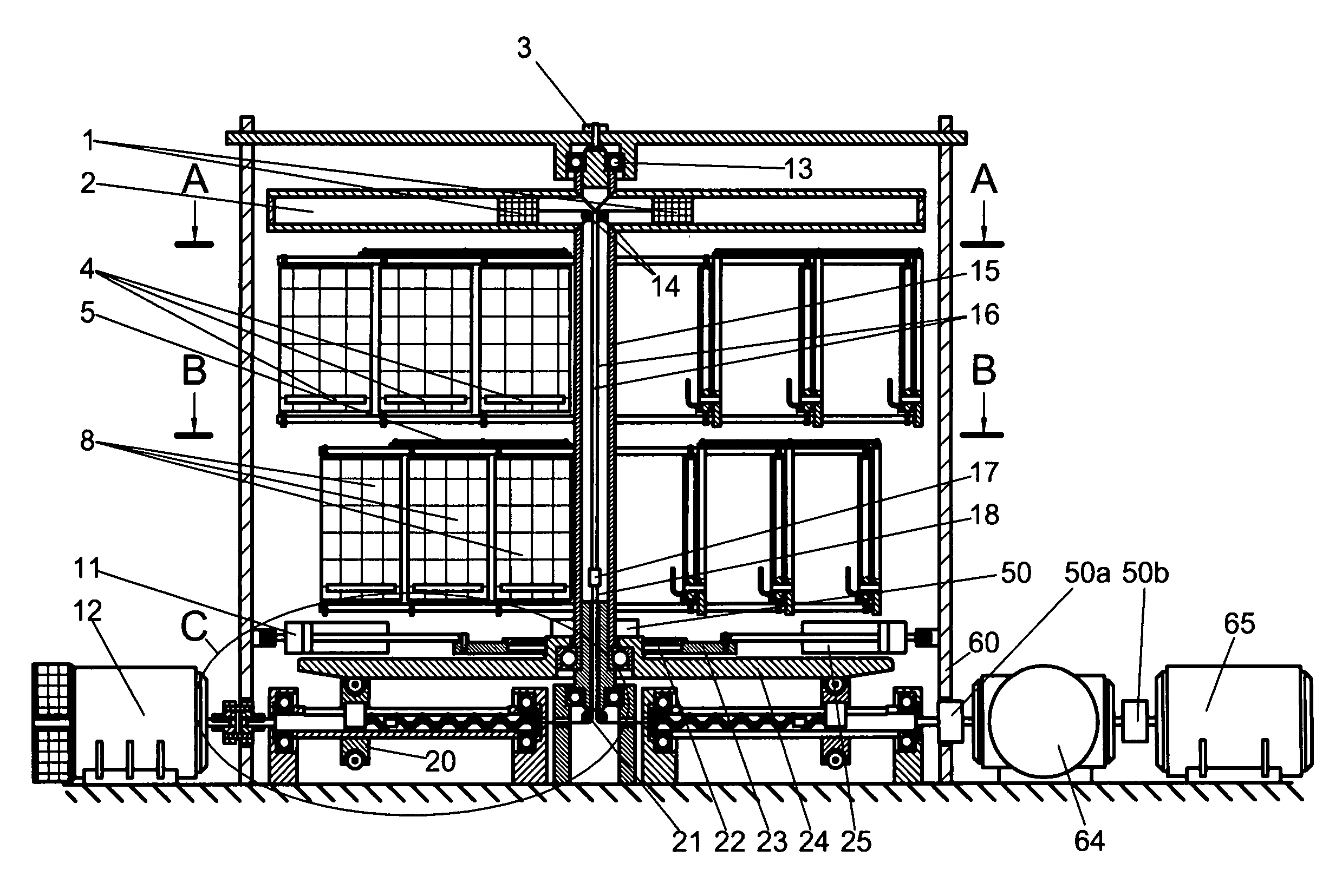
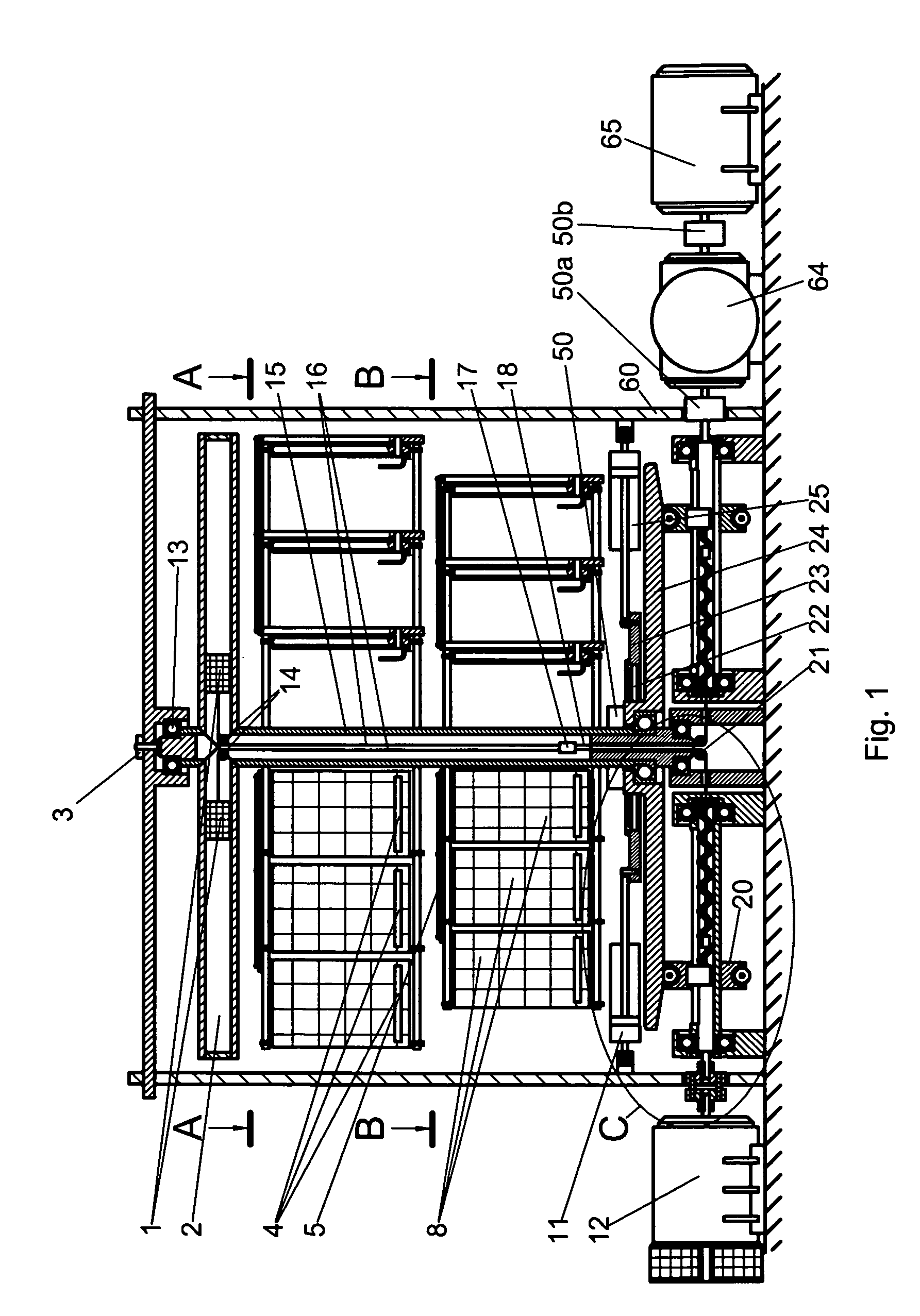
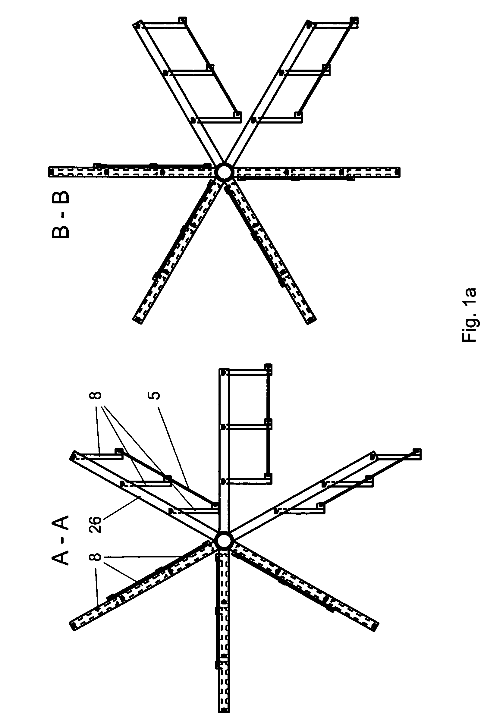
[0034]Referring to a preferred embodiment of the present invention illustrated on FIGS. 1, 1a, 1b, and 1c there is shown a windmill engine of the APS and parts of the engine. The windmill engine comprises a stationary frame (60), a main vertical shaft (15) supported by bearings (13) and (43) mounted in the frame 60. In preferred embodiments, the windmill engine comprises an upper carousel and a lower carousel of vertical pivotal vanes (8). In optional embodiments another number of carousels can be used.

[0035]The vanes 8 of the carousels are pivotally arranged on a number of hori...


PUM


Abstract

An airflow power station preferably comprises a windmill engine rotatable by wind including a main shaft and a rotational speed sensor, a compressed-air tank, a compressor charging the tank, an electric generator, a flywheel conveying rotation to the compressor and to the generator, and two pneumo-cylinders with pistons and sensors sensing their initial and ending positions. Each piston is coupled with a rod hingedly associated with a clutch controllably engaging and disengaging the piston with the flywheel. Each pneumo-cylinder is divided into an inner and an outer chamber, pneumatically communicating with the tank via an intake valve controllably supplying compressed air and a pneumo-regulator controllably switching the airflow ‘on’ and ‘off’ depending on the rotational speed of main shaft. Each pneumo-cylinder includes a reverse spring disposed in the inner chamber thereof, compressed during a work stroke of the piston and released upon return of the piston into its initial position.

Description

FIELD OF THE INVENTION[0001]The present invention relates to ecologically clean renewable energy generating devices, more particular to windmill devices capable of accumulating excessive wind energy during periods of a high wind flow and deploying the accumulated energy during periods of a low wind flow for electric power generation. The invention is especially usable as a supplemental electric energy source being mounted on residential and commercial buildings, which supplemental source is preferably associated with a common electric distribution grid.BACKGROUND OF THE INVENTION AND RELATED ART[0002]The most recent economy trend in terms of power generation is directed towards renewable energy sources saving the environment and capable of insuring a certain extent of energy independence for consumers of power. One of the most significant such sources is the conversion of wind energy into electric energy that may be conveniently used by a lot of industrial and commercial facilities,...

Claims


Application Information

Patent Timeline
IPC IPC(8): F03D9/02
CPCF03D9/001F03D9/028F05B2240/40Y02E60/15Y02B10/30Y02E10/725Y02E10/728F05B2240/911F03D9/17F03D9/12Y02E60/16F03D9/28F03D9/25Y02E10/72Y02E70/30
Inventor BLANK, ANATOLYBLANK, LEONIOBLANK, EMIL
Owner BLANK ANATOLY
Why Eureka
Try Eureka