Permanent magnet rotating machine

a permanent magnet, rotating machine technology, applied in dynamo-electric machines, magnetic circuit shapes/forms/construction, electrical apparatus, etc., can solve the problems of increasing the loss of copper in the stator winding, deteriorating the efficiency of the motor, and generating noise and vibration. , to achieve the effect of reducing noise and vibration and improving efficiency

Active Publication Date: 2009-10-20
AICHI ELECTRIC
View PDF27 Cites 54 Cited by
  • Summary
  • Abstract
  • Description
  • Claims
  • Application Information

AI Technical Summary

Benefits of technology

[0024]Recently, as for permanent magnet motors for driving a compressor, not only improvement in efficiency but reduction of noise and vibration is highly desired.
[0025]Accordingly, it is an object of the present invention to provide a technique for achieving higher efficiency than the known permanent magnet rotating machines and for reducing cogging torque which is one of the factors that cause noise and vibration.
[0027]With this construction, a wide gap is not formed in the region of the central portion of the main magnetic pole in the circumferential direction between the outer circumferential surface of the rotor and the teeth top surface of the stator, so that reduction of magnetic flux can be prevented. Therefore, it is not necessary to increase the number of turns of the stator winding in order to maintain the induced electromotive force of the stator winding. Thus, a loss which may be caused by increase in the number of turns of the stator winding can be reduced. Further, magnetic flux can be prevented from being abruptly changed when the boundary portions between the first outer circumferential surface portions and the second outer circumferential surface portions pass the teeth. Therefore, the harmonic components contained in the induced electromotive force of the stator winding can be reduced, so that efficiency reduction due to the harmonic components contained in the induced electromotive force can be prevented.
[0029]With this construction, magnetic flux generated at the permanent magnet can be prevented from being short-circuited via the teeth of the stator. Thus the cogging torque which may be produced by short-circuit of the magnetic flux can be reduced.
[0031]In another aspect of the present invention, it is constructed such that [{0.08×(g+D)} mm≦h≦{0.6×(g+D)}mm], where g is a minimum distance(gap) between the outer circumferential surface of the rotor and the teeth top surface, D is a maximum distance between a virtual outer circumferential surface which has a radius corresponding to the longest distance between the center of the rotor and the outer circumferential surface of the rotor, and the outer circumferential surface portion of the auxiliary magnetic pole, and h is a minimum depth of the recess. With this construction, the cogging torque can be further reduced.
[0032]In another aspect of the present invention, it is constructed such that [0.5≦D / g≦1.6], where g is a minimum distance between the outer circumferential surface of the rotor and the teeth top surface, and D is a maximum distance between a virtual outer circumferential surface which has a radius corresponding to the longest distance between the center of the rotor and the outer circumferential surface of the rotor, and the outer circumferential surface portion of the auxiliary magnetic pole. With this construction, the cogging torque can be further reduced.

Problems solved by technology

The abrupt change of the magnetic flux through the teeth may cause generation of noise and vibration.
However, if the number of turns of the stator winding is increased, the copper loss of the stator winding increases, so that the efficiency of the motor is deteriorated.
When the rotor position detecting accuracy drops off, an optimum control cannot be achieved, and thus the motor efficiency is reduced.
In the distributed winding type, compared with the concentrated winding type, a larger amount of the stator winding sticks out of the slots, and thus a larger copper loss of the stator winding is caused.

Method used


Image

  • Permanent magnet rotating machine
  • Permanent magnet rotating machine
  • Permanent magnet rotating machine

Examples


first embodiment

[0090]Next, the construction of the permanent magnet motor 30 of the first embodiment will be explained in further detail with reference to FIGS. 3 and 4. FIG. 3 is a cross section of the permanent magnet motor 30 as viewed from the direction perpendicular to the axial direction. FIG. 4 is an enlarged view of an essential part of FIG. 3.

[0091]In this embodiment, the rotor 50 having four poles (two pairs of poles) is used. In other embodiments in this invention which will be described below, rotors having four poles (two pairs of poles) are also used.

[0092]In the rotor 50, main magnetic poles and auxiliary magnetic poles alternate in the circumferential direction when viewed in cross section (perpendicular to the axial direction). Magnet insert holes are provided in the main magnetic poles.

[0093]In the following description, the main magnetic poles are represented by main magnetic poles [A] to [D] and the auxiliary magnetic poles are represented by auxiliary magnetic poles [AB] to [D...

second embodiment

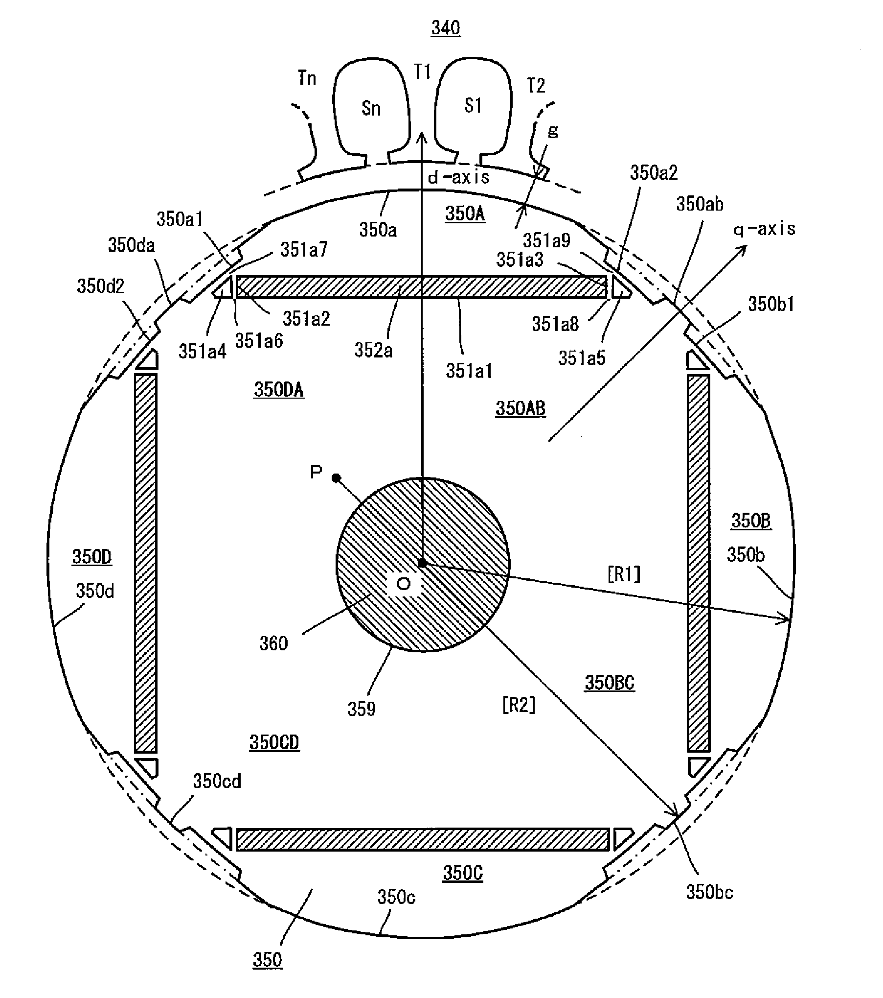
[0164]A rotor 150 of a second embodiment shown in FIG. 13 is different from the rotor 50 of the first embodiment in that spaces (non-magnetic regions) are provided between outer end walls of the magnet insert holes and recesses.

[0165]In a main magnetic pole 150A of the rotor 150 of the second embodiment, magnet insert holes 151a1, 151a3 are arranged in V-shape as viewed from the center O of the rotor 150. Permanent magnets 152a1, 152a2 having a rectangular cross section are inserted into the magnet insert holes 151a1, 151a3.

[0166]In the second embodiment, the permanent magnets 152a1, 152a2 are inserted into the magnet insert holes 151a1, 151a3 such that no spaces are formed between the permanent magnets 152a1, 152a2 and outer end walls 151a2, 151a4 of the magnet insert holes 151a1, 151a3. Spaces (non-magnetic regions) 151a5, 151a6 are provided between the outer end walls 151a2, 151a4 of the magnet insert holes 151a1, 151a3 and second outer circumferential surface portions 150da, 150...

third embodiment

[0168]A rotor 250 of a third embodiment shown in FIG. 14 is different from the rotor 50 of the first embodiment in the shapes of the magnet insert holes and the permanent magnets.

[0169]In a main magnetic pole 250A of the rotor 250 of the third embodiment, a magnet insert hole 251a1 having a circular arc cross section is provided. The circular arc shape is formed to bulge toward the center of the rotor. A permanent magnet 252a having generally the same cross section as the magnet insert hole 251a1 is inserted into the magnet insert hole 251a1.

[0170]In the rotor 250 of this embodiment, no spaces are provided between the permanent magnet 252a and second outer circumferential surface portions 250da, 250ab (the bottoms of recesses 250a1, 250a2).


PUM


Abstract

Permanent magnets 52a1, 52a2 are inserted into magnet insert holes 51a1, 51a4 formed in a main magnetic pole 50A of a rotor 50. An outer circumferential surface of the rotor includes a first outer circumferential surface portion 50a which intersects with a d-axis and second outer circumferential surface portions 50da, 50ab which intersect with a q-axis. A radius R2 of curvature of the second outer circumferential surface portions 50da, 50ab is larger than a radius of curvature of the first outer circumferential surface portions 50a. Recesses 50a1, 50a2 are formed in the second outer circumferential surface portions 50da, 50ab and in a position to face end walls 51a2, 51a5 of the magnet insert holes 51a1, 51a4 which are adjacent to the outer circumferential surface of the rotor. It is constructed such that [(74 / P)°≦θ≦(86 / P)°] and [(16 / P)°≦α≦(48 / P)°], where θ is a mechanical angle of the first outer circumferential surface portion 50a, P is the number of pairs of poles of the rotor 50, and α is a mechanical angle of the recesses 50a1, 50a2.

Description

BACKGROUND OF THE INVENTION[0001]1. Field of the Invention[0002]The present invention relates to a permanent magnet rotating machine, and more particularly, to a permanent magnet rotating machine in which permanent magnets are inserted into magnet insert holes formed in a rotor.[0003]2. Description of the Related Art[0004]Generally, a permanent magnet motor having a rotor in which permanent magnets are inserted into magnet insert holes is used as a motor for driving a compressor which is installed, for example, in an air conditioner or a refrigerator, or as a motor for driving a vehicle or a motor for driving an apparatus installed in a vehicle. Such a permanent magnet motor is typically referred to as an “interior permanent magnet motor (IPM motor)”.[0005]In the permanent magnet motor, generally, a stator has teeth that define slots for holding a stator winding. The rotor is rotatably disposed such that a gap is formed between the outer circumferential surface of the rotor and the ...

Claims


Application Information

Patent Timeline
Patent Type & Authority Patents(United States)
IPC IPC(8): H02K21/12
CPCH02K1/276H02K29/03H02K1/2766
Inventor OKUMA, SHIGERUDOKI, SHINJITOMITA, MUTSUOSATO, MITSUHIKOKANEKO, SEIICHI
Owner AICHI ELECTRIC
Why Eureka
Try Eureka