Controlled bleeder for power supply

a power supply and control technology, applied in the field of power supplies, can solve the problems of additional limitations on the timing control of pwm, high cost of large plurality of power sources, etc., and achieve the effect of stable power

Inactive Publication Date: 2009-10-20
POLARIS POWERLED TECH LLC
View PDF9 Cites 26 Cited by
  • Summary
  • Abstract
  • Description
  • Claims
  • Application Information

AI Technical Summary

Benefits of technology

[0014]Accordingly, it is a principal object of the present invention to overcome the disadvantages of prior art. This is provided in the present invention by a controlled bleeder associated with each power source. In one embodiment the controlled bleeder comprises an impedance arranged to be controllably switched to present a load to the power source, and in an other embodiment the controlled bleeder comprises a current source arranged to be controllably draw a pre-selected current from the power source. In an exemplary embodiment the controlled bleeder is switched to draw current just prior to enabling one or more LED strings so as to absorb any ringing from the power supply. Thus, the LED strings experience more stable power when connected to draw power.
[0016]In another embodiment the controlled bleeder is operative to provide one of a plurality of current levels. In yet another embodiment the controlled bleeder exhibits a time dependent current draw which acts to reduce ringing. Reduced ringing is advantageous to reduce electromagnetic interference as well as to provide a stable current for the LED string. In yet another embodiment the controlled bleeder is operated during any large shift in current draw so as to reduce ringing.
[0021]In one embodiment the controlled bleeder is arranged to draw a pre-determined bleed current from the power source. In another embodiment the control circuit is operative to draw a time dependent amount of bleed current, and wherein the time dependent amount of bleed current is operative to reduce electromagnetic interference. In yet another embodiment the control circuit is operative to draw the bleed current prior to the at least one LED string being switchably connected to draw current, wherein the drawn bleed current reduces ringing experienced by the at least one LED string.
[0027]In one embodiment the bleed current is selected from a plurality of pre-determined levels of current. In another embodiment the bleed current is of an adjustable amount. In another embodiment the bleed current is a pre-determined amount of current. In yet another embodiment the bleed current is of a time adjustable amount, the time adjustable amount reducing electromagnetic interference. In yet another embodiment the drawing of the bleed current is just prior to the drawing current from the power source via the provided at least one LED string, and wherein the bleed current reduces ringing of the drawn current.

Problems solved by technology

Such a large plurality of power sources effectively minimizes excess power dissipation however the requirement for a large plurality of power sources is costly.
Unfortunately, since as indicated above different LED strings of the same color may exhibit different voltage drops, such a solution further requires an active element in series with each LED string to compensate for the difference among the respective voltage drops so as to ensure an essentially equal current through each of the LED strings of the same color.
Ideally, the power source used should have a high frequency response, and thus be capable of supporting the rapidly changing load, but unfortunately this is costly.
Unfortunately, this puts an additional limitation on the PWM timing control, and may not always achievable.
Furthermore, in the event that the control for the LED strings samples the amount of current flowing through each LED string, care must be taken to ensure that a sample is not obtained during the ringing, as such a sample may not be representative of the actual current flow.

Method used


Image

  • Controlled bleeder for power supply
  • Controlled bleeder for power supply
  • Controlled bleeder for power supply

Examples


first embodiment

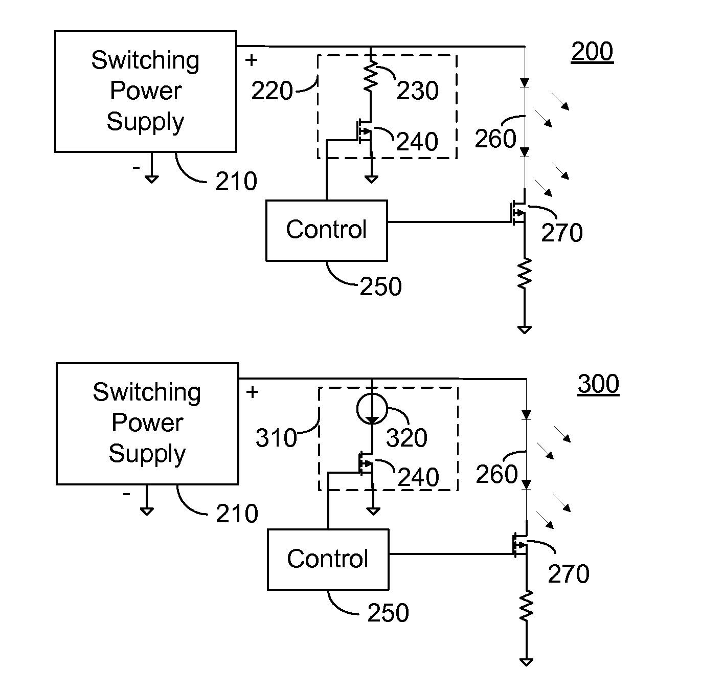
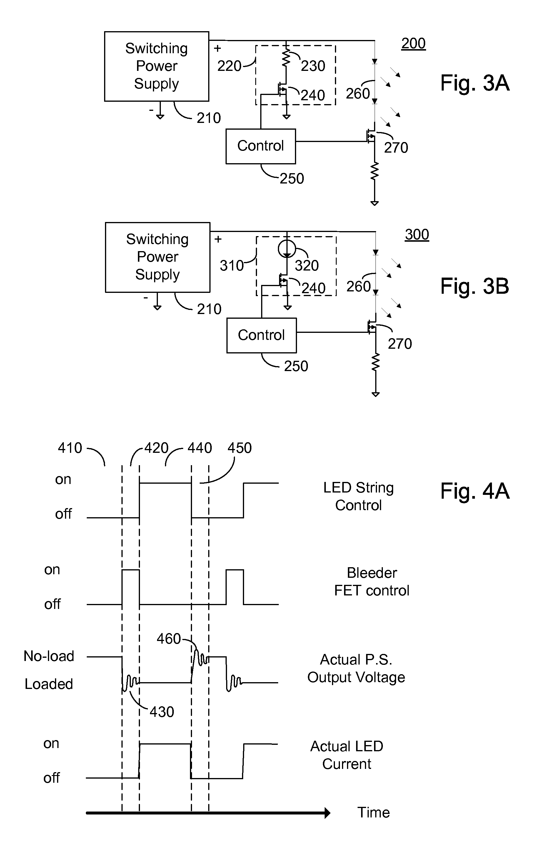
[0056]FIG. 4A illustrates the control signal for electronically controlled switch 270 associated with LED string 260 of FIGS. 3A, 3B; the control output associated with controlled bleeder 220, 310 of FIGS. 3A, 3B respectively in accordance with a principle of the invention, in which the bleeder is controlled to act responsive to a step input; the actual output voltage of the power source of FIGS. 3A, 3B; and the actual LED string current of FIGS. 3A, 3B in accordance with a principle of the invention. The waveforms of FIG. 4A are illustrated in relation to a common x-axis representative of time, with the y-axis of each respective waveform being representative of voltage or current respectively.

[0057]During time period 410, LED string 260 is controlled by electronically controlled switch 270 so as not to conduct, and thus the output of switching power supply 210 exhibits an unloaded condition, which is typically the maximum output voltage of switching power supply 210. During time pe...

second embodiment

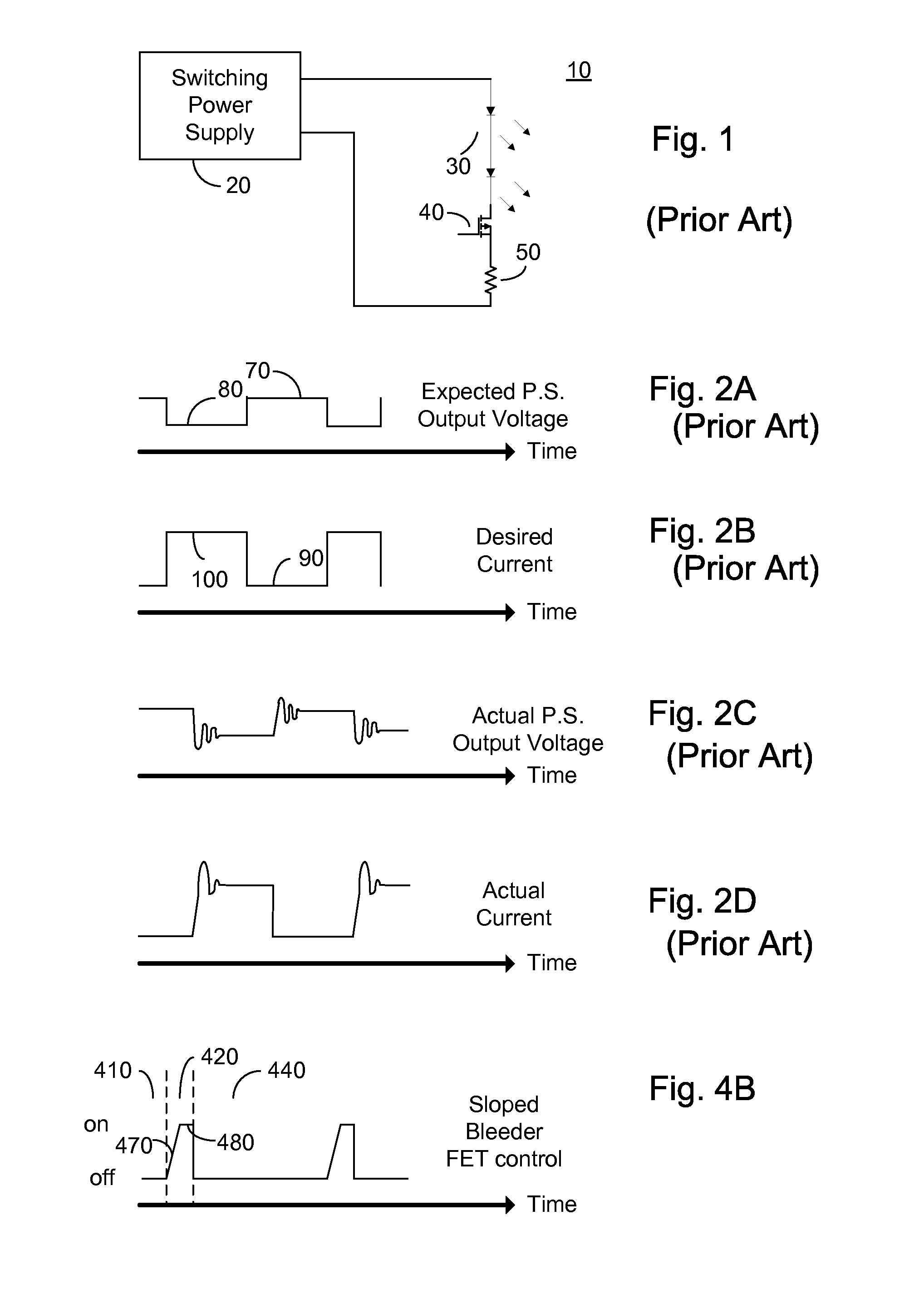
[0061]FIG. 4B illustrates the operation of controlled bleeder 220, 310 of FIGS. 3A, 3B in accordance with a principle of the invention, in which the controlled bleeder is controlled to act responsive to a sloped input. In FIG. 4B the y-axis indicates the control signal for electronically controlled switch 240 and the x-axis time. Controlled bleeder 220, 310 of FIGS. 3A and 3B respectively are controlled to act responsive to a gradual input as shown by slope 470, thereby drawing a time dependent bleed current so as to minimize the ringing of switching power supply 210. During timing period 420, which as described above in relation to FIG. 4A, begins a pre-determined time prior to time period 440 of FIG. 4A and ends substantially contemporaneously with the beginning of time period 440, control 250 activates controlled bleeder 220, 310 to gradually increase the amount of current drawn by controlled bleeder 220. During time period 440, control 250 deactivates controlled bleeder 220, 310...


PUM


Abstract

An LED backlighting system including: a control circuit; a power source; at least one LED string associated with the power source, the at least one LED string being arranged to be switchably connected to alternatively draw an illumination current from the power source and not draw an illumination current from the power source; and a controlled bleeder arranged to draw a bleed current from the power source responsive to the control circuit; the control circuit being operative to draw the bleed current from the power source via the controlled bleeder for a predetermined time period associated with the alternatively drawing and not drawing the illumination current of the at least one LED string.

Description

CROSS-REFERENCE TO RELATED APPLICATIONS[0001]This application claims priority from U.S. Provisional Patent Application Ser. No. 60 / 807,503 to Ferentz et al, filed Jul. 17, 2006 and entitled “CONTROLLED BLEEDER FOR POWER SUPPLY”, the entire contents of which is incorporated herein by reference.BACKGROUND OF THE INVENTION[0002]The present invention relates to the field of power supplies for light emitting diode based backlighting and more particularly to a controlled bleeder timed to absorb and or limit any power supply ringing.[0003]Light emitting diodes (LEDs) and in particular high intensity and medium intensity LED strings are rapidly coming into wide use for lighting applications. LEDs with an overall high luminance are useful in a number of applications including backlighting for liquid crystal display (LCD) based monitors and televisions, collectively hereinafter referred to as a monitor. In a large LCD monitor typically the LEDs are supplied in one or more strings of serially ...

Claims


Application Information

Patent Timeline
Patent Type & Authority Patents(United States)
IPC IPC(8): H05B37/00G06F3/038
CPCH05B33/0815H05B33/0857H05B33/0827H05B33/0818H05B45/46H05B45/28H05B45/3725
Inventor FERENTZ, ALONBLAUT, RONI
Owner POLARIS POWERLED TECH LLC
Why Eureka
Try Eureka