Virtual path configuration apparatus, virtual path configuration method, and computer product

Inactive Publication Date: 2009-10-20
FUJITSU LTD
View PDF18 Cites 328 Cited by
  • Summary
  • Abstract
  • Description
  • Claims
  • Application Information

AI Technical Summary

Benefits of technology

[0024]It is an object of the present invention to solv

Problems solved by technology

However, it has not widely spread because it has taken a long time to standardize enormous specifications and low-priced Ethernet (Registered Trademark) has spread quickly.
Further, packet processing becomes complicated, performance may not be able to be heightened, or expensive equipment is possibly necessary to heighten the performance.
Further, when many branches are present, configuration of routers con

Method used


Image

  • Virtual path configuration apparatus, virtual path configuration method, and computer product
  • Virtual path configuration apparatus, virtual path configuration method, and computer product
  • Virtual path configuration apparatus, virtual path configuration method, and computer product

Examples


Embodiment Construction

[0061]Exemplary embodiments of a virtual path configuration apparatus and a virtual path configuration method according to the present invention are explained in detail below with reference to the accompanying drawings.

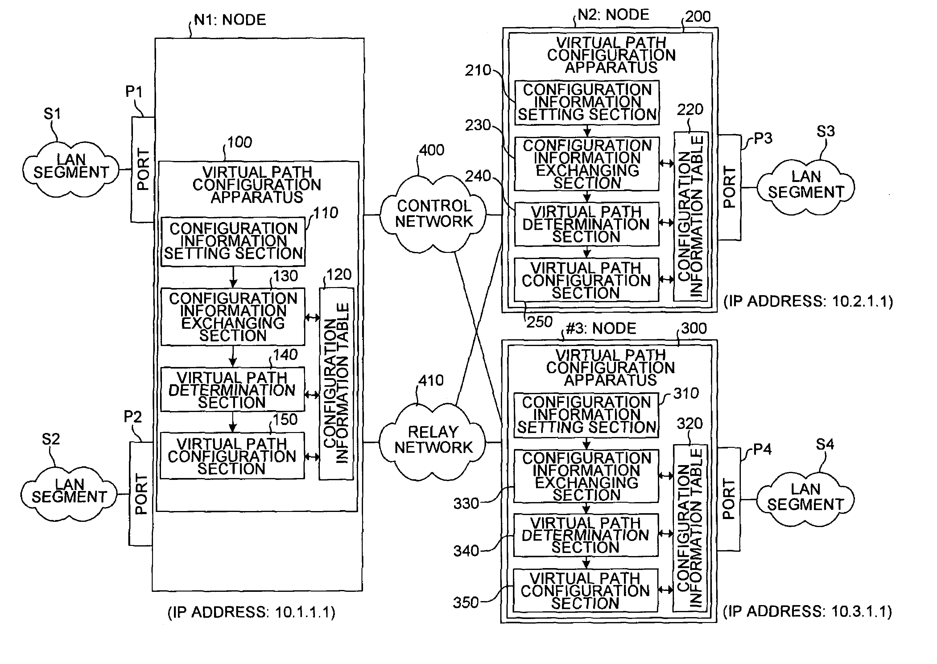
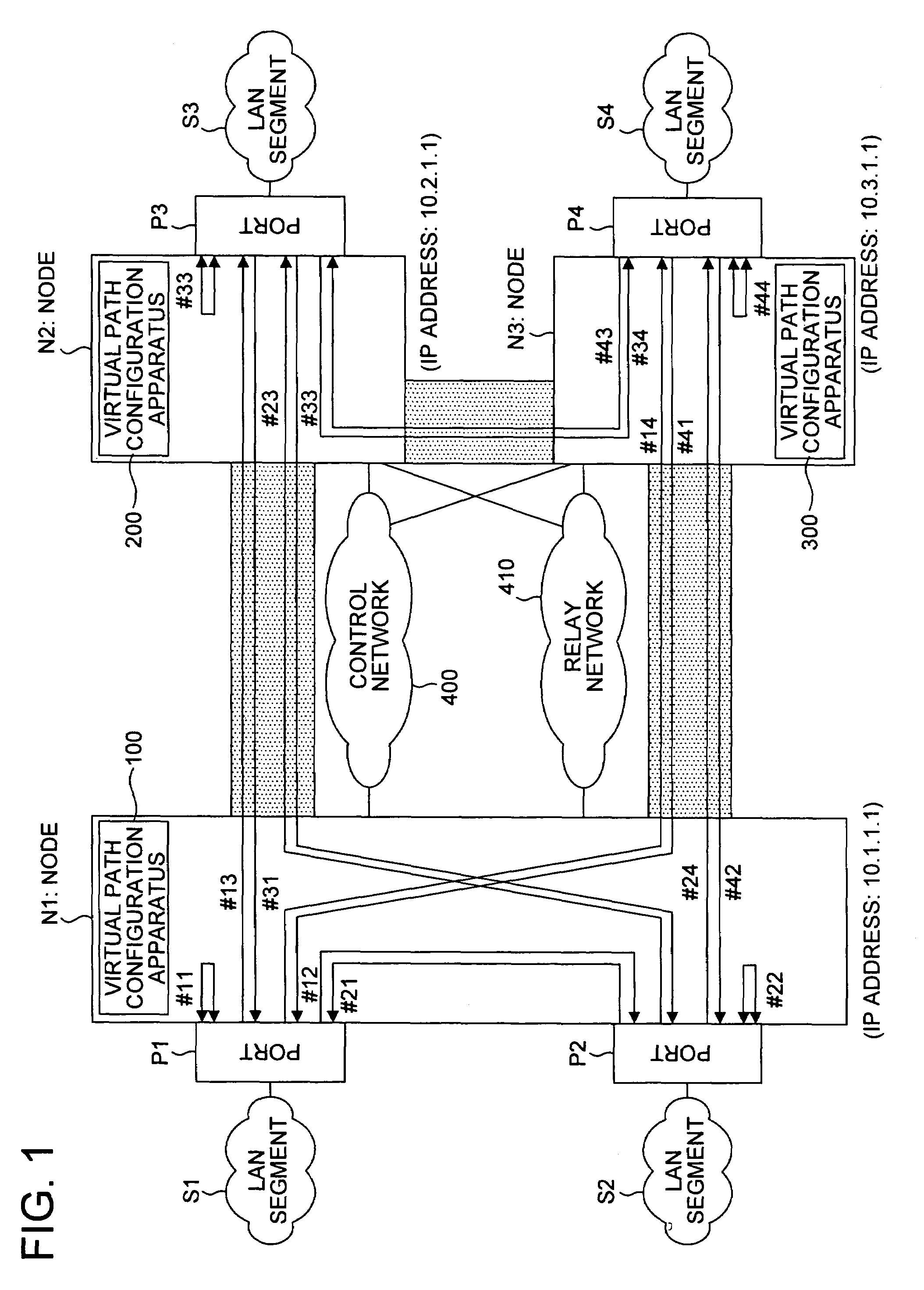
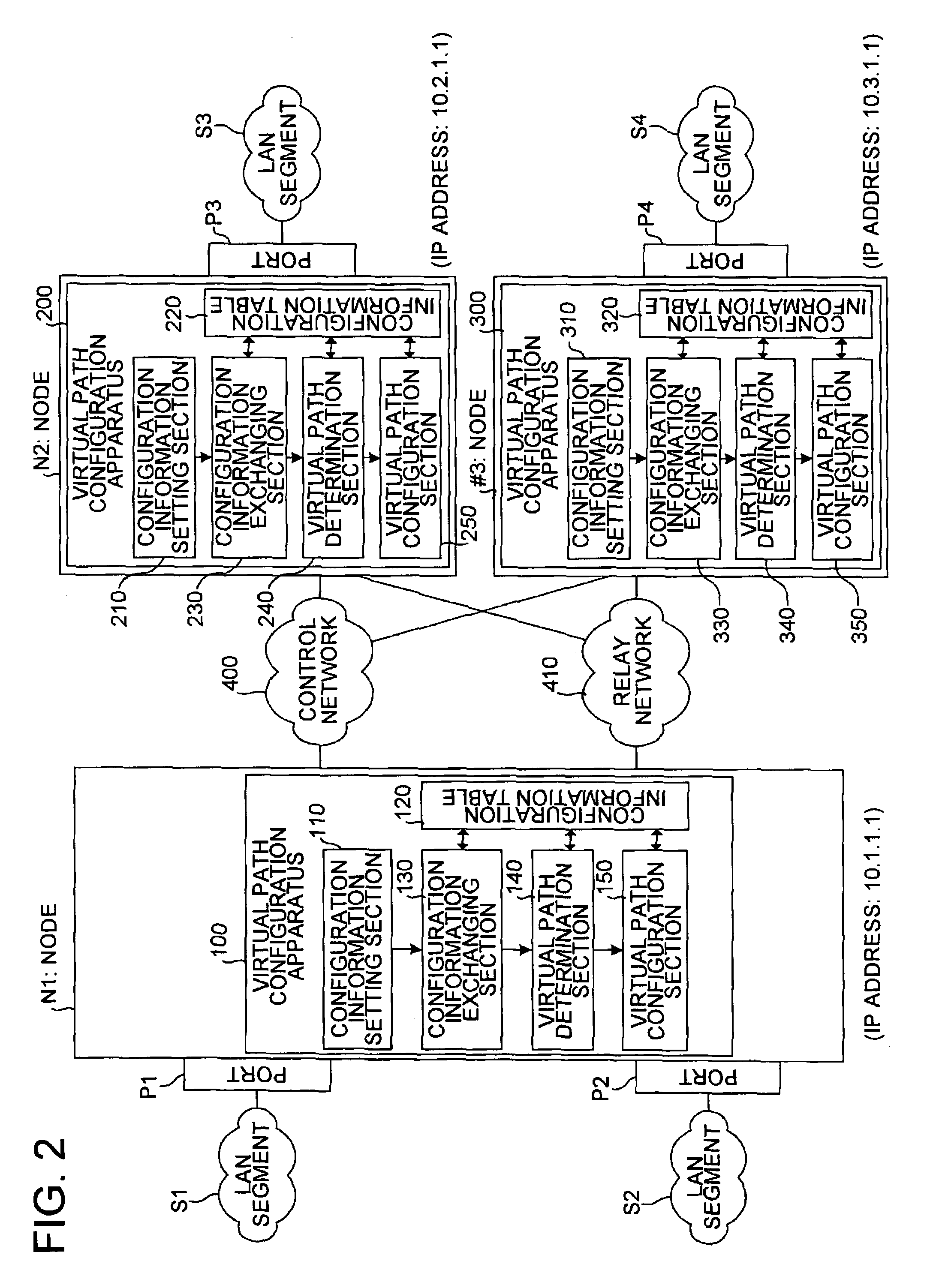
[0062]FIG. 1 is to explain how a virtual path is constructed according to an embodiment of the present invention in a VPN. Structural elements that perform same or similar functions or have same or similar configuration as those in FIG. 34 are designated by same reference numbers. As compared to FIG. 34, virtual path configuration apparatuses 100, 200, and 300 have been provided, and the consoles C1, C2, and C3 have been omitted.

[0063]The nodes N1, N2, and N3 are connected with each other via a control network 400 and a relay network 410. The control network 400 is used for configuring a virtual path in VPN and transmitting various information relating to establishment of connection between the nodes. Meanwhile, the relay network 410 is used for relaying data packet a...


PUM


Abstract

Configuration information set in one virtual path configuration apparatus is shared with all the virtual path configuration apparatuses in the virtual private network. The configuration information may be shared by transmitting the configuration information to other virtual path configuration apparatuses or receiving configuration information from the other virtual path configuration apparatuses.

Description

BACKGROUND OF THE INVENTION[0001]1) Field of the Invention[0002]The present invention relates to a technology for configuring a virtual path of a virtual private network (VPN).[0003]2) Description of the Related Art[0004]Recently, as the Internet spreads, companies that use the Internet (hereinafter, “user companies”) are able to connect their branches without utilizing a virtually leased line service such as Asynchronous Transfer Mode (ATM) and a frame relay.[0005]As to utilization in wide area network (WAN), a commercial communication service has started in 1994 in the United States, and a service of “super relay CR” has started by Nippon Telegraph and Telephone Corporation (NTT) in 1995 in Japan. In the next-generation B-ISDN proposed by NTT, a transmission speed was supposed to be heightened and public communication lines were supposed to be integrated based on ATM technology.[0006]On the other hand, the development of ATM-LAN in which the ATM technology is applied to local area...

Claims


Application Information

Patent Timeline
IPC IPC(8): H04J3/22H04L12/70H04L12/46H04L12/755
CPCH04L12/4675H04L12/5601H04L2012/5624H04L2012/5621
Inventor OGUCHI, NAOKITSURUOKA, TETSUMEIKUBOTA, MAKOTO
Owner FUJITSU LTD
Why Eureka
Try Eureka