Optical communication system, optical reader, and method of reading information

a communication system and optical reader technology, applied in the field of optical communication systems, optical readers, and methods of reading information, can solve problems such as information not being transmitted

Inactive Publication Date: 2009-10-20
SONY CORP
View PDF9 Cites 63 Cited by
  • Summary
  • Abstract
  • Description
  • Claims
  • Application Information

AI Technical Summary

Benefits of technology

[0019]According to the present invention, the optical reader can read out the identification information stored in the target optical ID tag even if other optical ID tags exist in the vicinity of the target optical ID tag and light is incident on the other optical ID tags at angles of incidence similar to the angle of the incidence of the target optical ID tag. Consequently, it is possible to realize the optical communication system the optical reader, and the method of reading information, which are capable of appropriately communicating the identification information.

Problems solved by technology

However, the optical ID tag having the above structure has a problem in that, if multiple light beams have been emitted at similar angles of incidence, the identification information is not transmitted to the optical readers that have emitted the light beams at the similar angles of incidence or different pieces of identification information are simultaneously transmitted to the optical readers, because the reflected light beams converge in the incident direction (a congestion state).

Method used


Image

  • Optical communication system, optical reader, and method of reading information
  • Optical communication system, optical reader, and method of reading information
  • Optical communication system, optical reader, and method of reading information

Examples


Embodiment Construction

[0029]Embodiments of the present invention now will be described in detail with reference to the attached drawings.

Structure of Optical Communication System

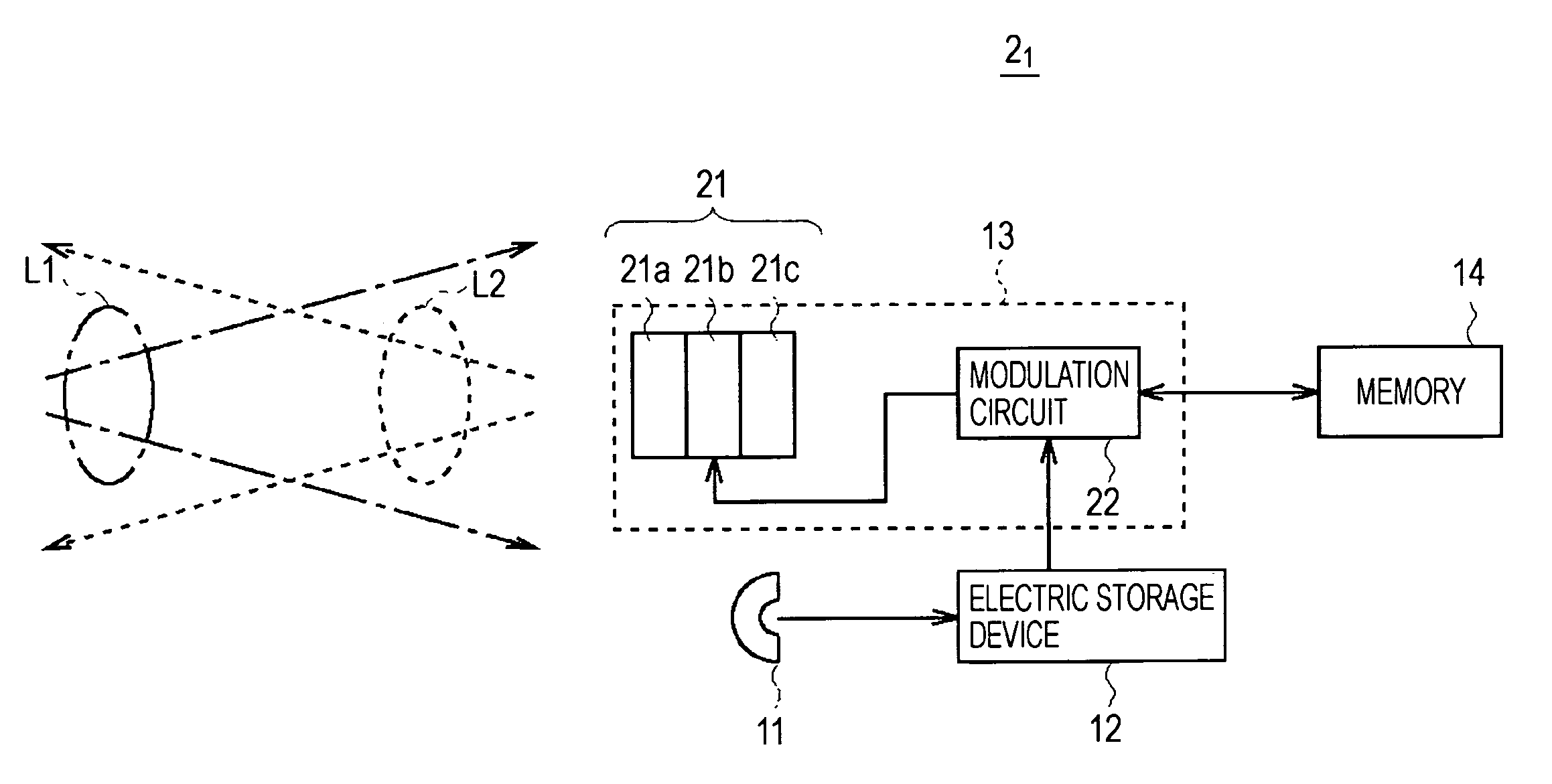
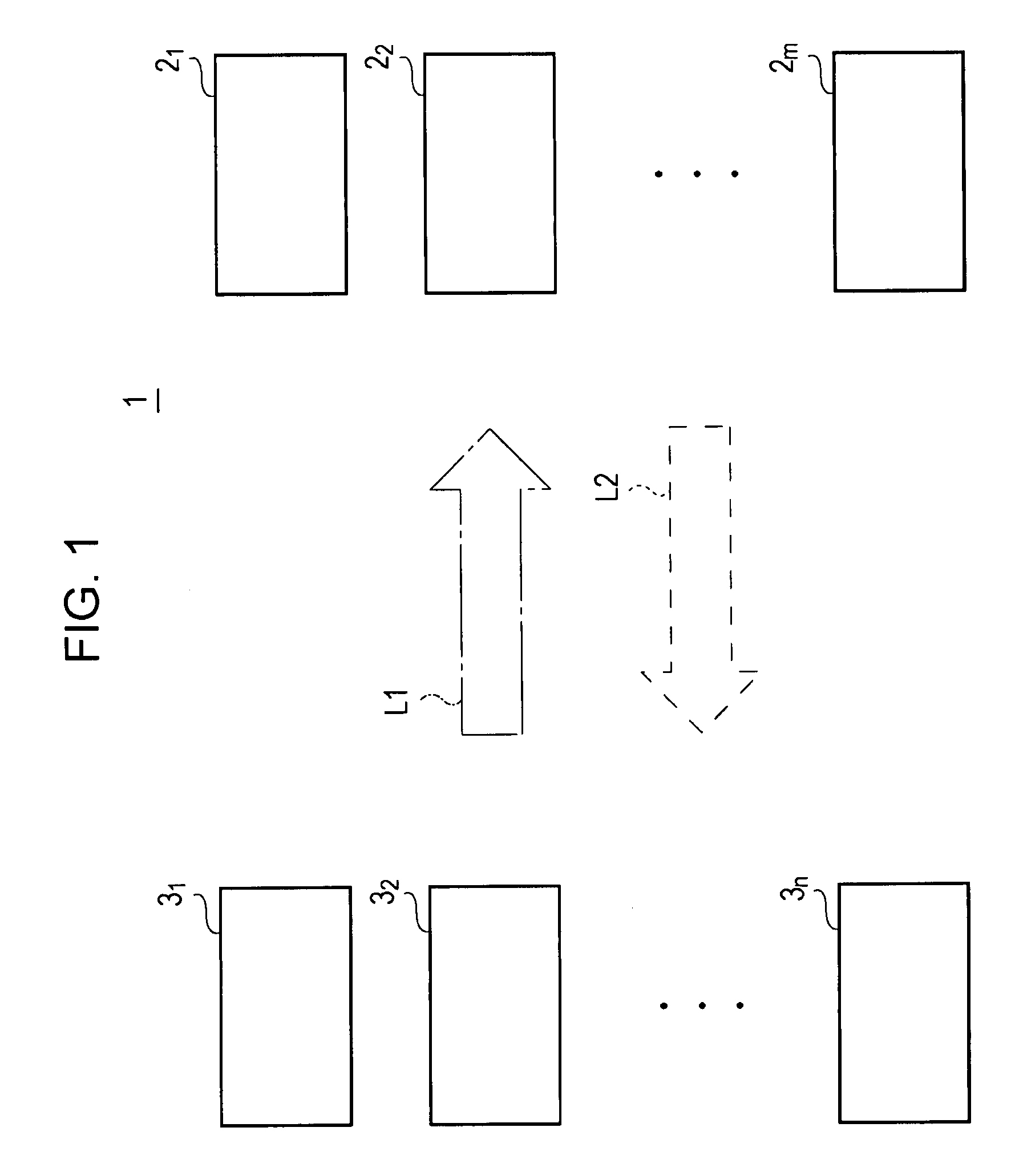
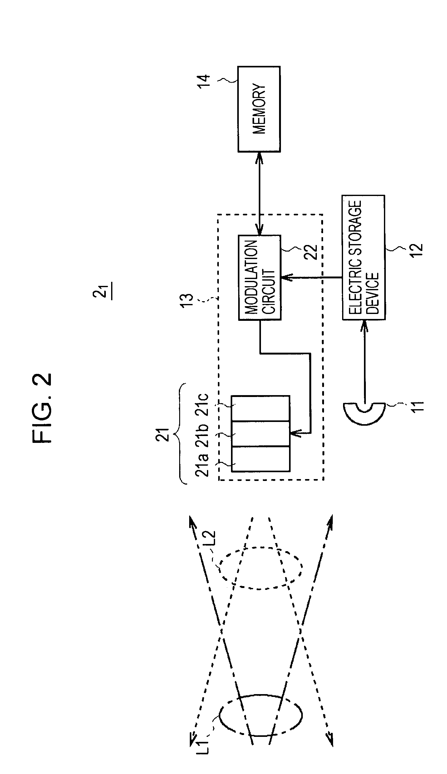
[0030]FIG. 1 shows an example of the entire structure of an optical communication system 1 according to an embodiment of the present invention. The optical communication system 1 includes multiple optical ID tags and multiple optical readers. Each optical ID tag is denoted by an optical ID tag 2i (“i” is equal to 1, 2, 3, . . . , or m (m is an integer)), and each optical reader is denoted by an optical reader 3j (“j” is equal to 1, 2, 3, . . . , or n (n is an integer)).

[0031]The optical ID tag 2i is provided for a target article. Identification information concerning the target article is recorded in the optical ID tag 2i.

[0032]Specifically, for example, when the optical ID tags 21 to 2m are used to manage articles, the optical ID tag 2i is provided for each article, and manufacturing information concerning the article, such as t...


PUM


Abstract

An optical communication system includes at least one optical ID tag and at least one optical reader. Identification information is communicated between the optical ID tag and the optical reader using light as a communication medium. The optical ID tag includes storing units for storing the identification information; reflecting units for reflecting incident light in the incident direction; and modulating units for modulating reflected light on the basis of the identification information stored in the storing units. The optical reader includes random number generating units for generating a random number; emitting units for emitting light having an oscillation frequency specific to the generated random number; photoelectric conversion units for performing photoelectric conversion to the reflected light incident in the emitting direction; extracting units for extracting a signal component having the oscillation frequency from the signal resulting from the photoelectric conversion; and demodulating units for demodulating the signal component.

Description

CROSS REFERENCES TO RELATED APPLICATIONS[0001]The present invention contains subject matter related to Japanese Patent Application JP 2006-089009 filed in the Japanese Patent Office on Mar. 28, 2006, the entire contents of which are incorporated herein by reference.BACKGROUND OF THE INVENTION[0002]1. Field of the Invention[0003]The present invention relates to an optical communication system, an optical reader, and a method of reading information. The present invention is preferably applied to reading of identification information from compact wireless IC chips.[0004]2. Description of the Related Art[0005]Recently, radio frequency identification (RFID) has gained attention as a technology of identifying or managing articles, with which barcodes are replaced.[0006]In RFID, identification information specific to articles is stored in a compact wireless device called a wireless IC tag (or wireless IC chip) and the articles are identified or managed on the basis of the identification in...

Claims


Application Information

Patent Timeline
Patent Type & Authority Patents(United States)
IPC IPC(8): G02B6/28H04B10/11G06K17/00G06K19/07H04B10/114H04B10/80
CPCG06K7/1097G06K19/0728G06K19/0723
Inventor MORITA, TADASHI
Owner SONY CORP
Why Eureka
Try Eureka