

Mounting device for an aircraft engine comprising two thrust recovery rods with a double rear mechanical connection
a technology for aircraft engines and mounting devices, which is applied in the direction of machines/engines, other domestic objects, machine supports, etc., can solve the problems of generating mass and space requirements that are difficult to meet, and achieve the effect of facilitating the design of the thrust load recovery device and the mounting of the connection
- Summary
- Abstract
- Description
- Claims
- Application Information
AI Technical Summary
Benefits of technology
Problems solved by technology
Method used
Image

Examples
first embodiment
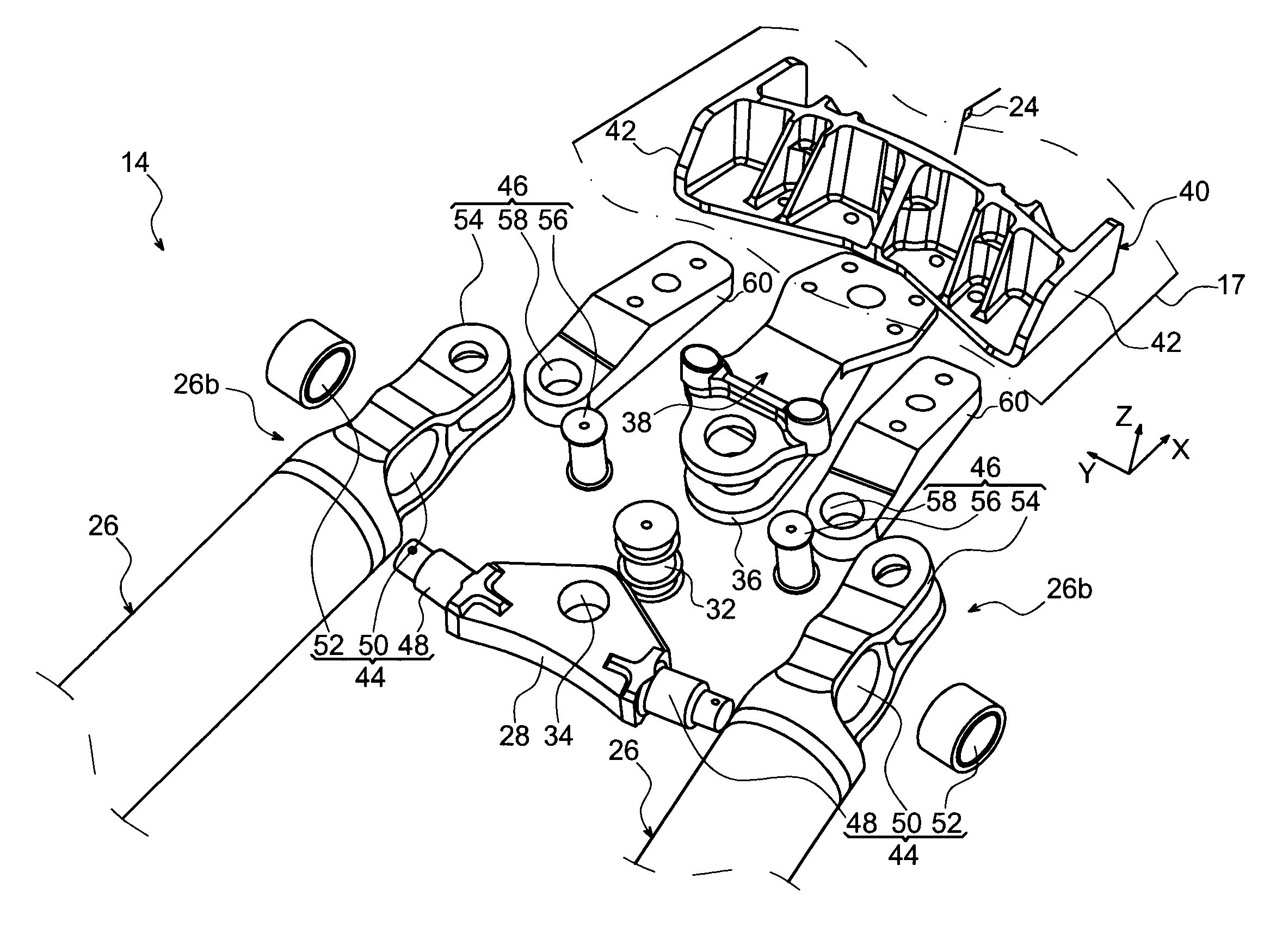
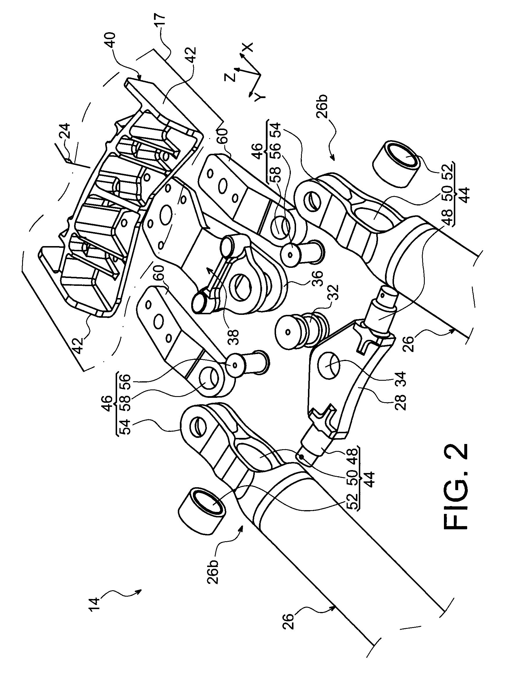
[0066]With reference now to FIG. 5, showing a rear part of the recovery device 14 according to a second preferred embodiment of the present invention, it can be seen that the main difference with the first embodiment described above lies in the design of the connection fitting 38 carrying the crossbar 28. As such, it should be noted that this figure taken in cross-section along the vertical and longitudinal median plane 24 of the mounting device, the elements bearing the same numerical references as in the other figures correspond to identical or similar elements.
[0067]The connection fitting 38 has an upper surface added in a fixed way under the lower spar 17 with which it is preferably in contact, the assembly means used (not shown), for example of the bolt type, coming to engage with a reinforcement fitting 40 housed inside the box, and being preferably in contact with the inner surface of the lower spar 17.
[0068]Nonetheless, unlike the first embodiment, it has an orifice to accom...
second embodiment
[0070]In FIG. 6 showing an alternative for implementing the second embodiment, it can be seen that only the connection of the support fittings 60 differs relative to that of the arrangement shown in FIG. 5, the connection of the crossbar 28 being in fact identical or similar to the one relating to the arrangement shown in this same FIG. 5. Indeed, the rear ends of the two support fitting is 60 (only one being visible in FIG. 6 because of the perspective view) are no longer added directly onto the lower spar 17, but are carried in a fixed way by a principal body 64 of the rear engine mount 12, itself mounted in a fixed way on the lower spar 17, underneath it. In this way, this arrangement constitutes another possibility allowing the two support fittings 60 to be made integral with the rigid structure 8, via the principal body 64 of the rear engine mount 12.
[0071]To be more precise, the principal body 64 forming devises and carrying connecting links, orientated substantially transvers...
PUM
 Abstract
Description
Claims
Application Information