
Printer

a printing machine and printing plate technology, applied in the field of printing machines, can solve problems such as the decrease of print quality, and achieve the effects of reducing the displacement of dots, and high-quality printing images

Inactive Publication Date: 2009-10-27
SEIKO EPSON CORP
View PDF3 Cites 33 Cited by
  • Summary
  • Abstract
  • Description
  • Claims
  • Application Information

AI Technical Summary

Benefits of technology

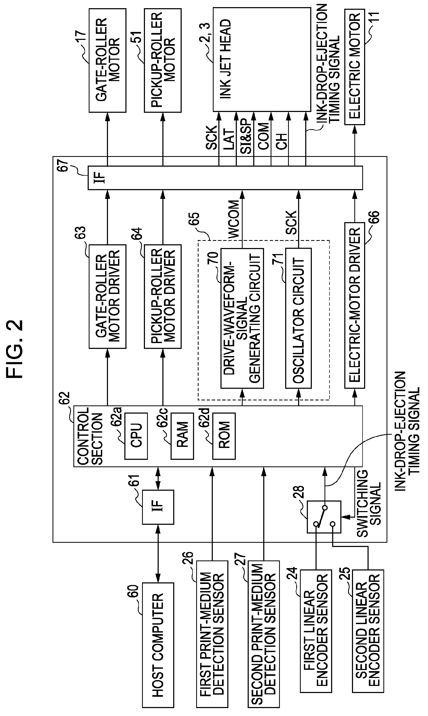
The invention provides a printer with multiple transporting units that can print high-quality images. The printer includes two transporting belts, two linear encoders, and a liquid ejection head. The printer can switch between the two transporting belts based on the phase difference between the two linear encoders. This reduces the displacement of dots during the switching, resulting in high-quality print images. The printer can also adjust the phase difference based on the distance between the two transporting belts to further improve the quality of the print images.

Problems solved by technology

Accordingly, the liquid cannot be ejected (dots cannot be formed) in correct positions, resulting in a decrease in print quality.

Method used


Image

  • Printer
  • Printer
  • Printer

Examples


Embodiment Construction

[0025]As an example of the printer of the invention, an ink jet printer according to an embodiment for printing characters or images on a print medium by ejecting ink will be described with reference to the drawings.

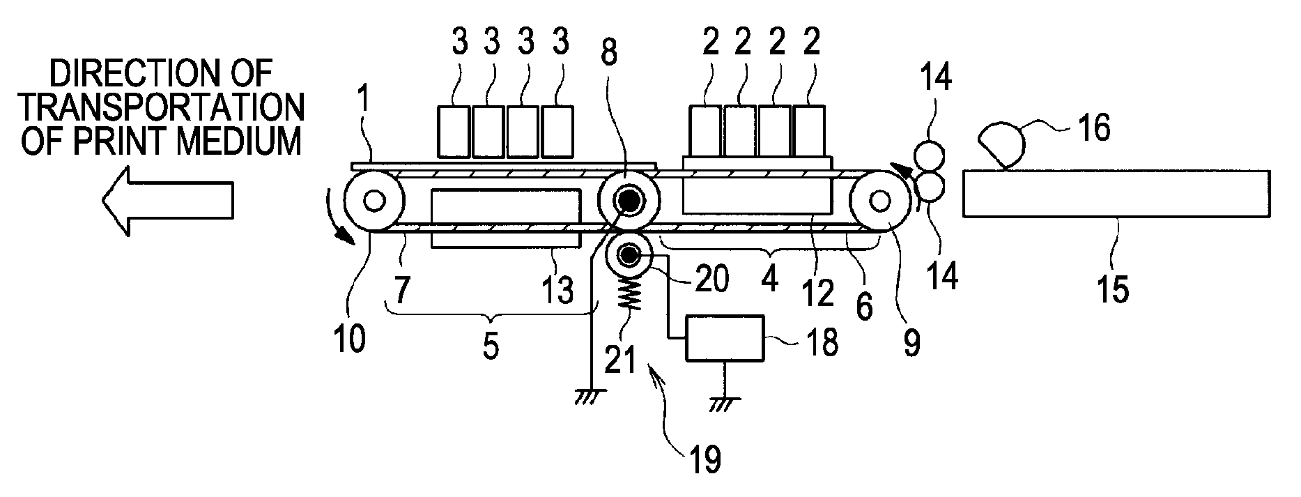
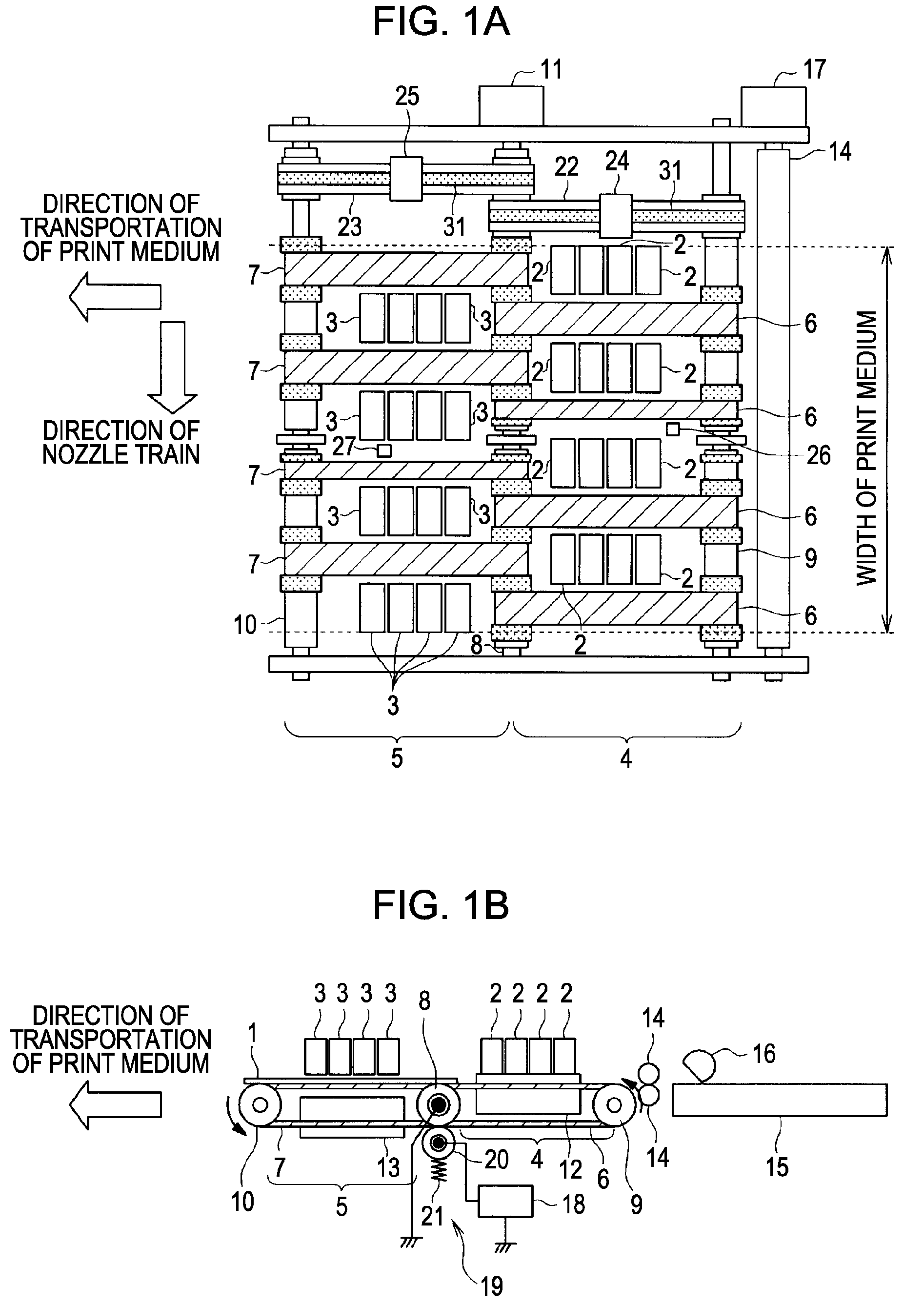
[0026]FIGS. 1A and 1B are schematic diagrams of the ink jet printer of this embodiment: FIG. 1A is a plan view thereof; and FIG. 1B is a side view thereof. The printer shown in FIGS. 1A and 1B is a line-head ink jet printer in which a print medium 1 is transported from the right to the left along the arrow, and is printed in a printing region midway through transportation. This embodiment has the ink jet head not only at one place but at two places.

[0027]Reference numeral 2 denotes a first ink jet head disposed upstream in the direction of transportation of the print medium 1, and reference numeral 3 denotes a second ink jet head disposed downstream of the transportation. A first transporting section 4 for transporting the print medium 1 is disposed below the first ink j...


PUM


Abstract

A printer includes a first transporting belt that transports a print medium and a second transporting belt that receives the print medium from the first transporting belt and further transports the print medium. A liquid ejection head ejects liquid according to a liquid-ejection timing signal to the print medium transported by the first transporting belt and the second transporting belt. A signal generator outputs the liquid-ejection timing signal according to a first signal and a second signal that correspond to the travel of the first and second transporting belts, respectively. When the phase difference between the first and second signals has a predetermined threshold value or less, the signal generator switches from outputting the liquid-ejection timing signal according to the first signal to outputting the liquid-ejection timing signal according to the second signal.

Description

BACKGROUND[0001]1. Technical Field[0002]The present invention relates to printers that print predetermined characters or images by ejecting liquid from multiple nozzles to form fine particles thereof (dots) onto a print medium.[0003]2. Related Art[0004]Ink jet printers, one of such printers, print predetermined characters or images onto a print medium to produce desired prints by discharging (ejecting) liquid (ink drops) from the nozzles of a liquid ejection head (also referred to as an ink jet head) to form fine ink dots onto the print medium while relatively moving the print medium and the ink jet head. Among them, printers that move an ink jet head placed on a moving body, called a carriage, in the direction intersecting the direction of transportation of print media are generally referred to as multipass ink jet printers. On the other hand, printers capable of so-called one-pass printing with an ink jet head that is long in the direction intersecting the direction of transportat...

Claims


Application Information

Patent Timeline
Patent Type & Authority Patents(United States)
IPC IPC(8): B41J29/38
CPCB41J11/007B41J29/38B41J11/008
Inventor TABATA, KUNIOSUZUKI, TOSHIYUKIOSHIMA, ATSUSHI
Owner SEIKO EPSON CORP
Learn More