LED lamp instantly dissipating heat as effected by multiple-layer substrates

a technology of led lamps and substrates, which is applied in the direction of fixed installation, lighting and heating apparatus, and ways, etc., can solve the problems of increasing installation, operation and maintenance costs, shortening the service life of led lamps, and difficult to satisfactorily dissipate heat, so as to prevent deterioration of the illumination quality of led lamps. , the effect of effective dissipation of hea

Inactive Publication Date: 2009-10-27
TAMKANG UNIVERSITY
View PDF10 Cites 88 Cited by
  • Summary
  • Abstract
  • Description
  • Claims
  • Application Information

AI Technical Summary

Benefits of technology

[0008]The object of the present invention is to provide a LED lamp including: a plurality of substrates juxtapositioned as multiple layers, each substrate having a plurality of light emitting diodes (LEDs) mounted thereon, whereby upon generation of heat by the LEDs, each substrate will form as a heat-dissipating plate in-situ in order that the multiple-layer substrates will instantly effectively dissipate the heat from the LEDs of the lamp outwardly for preventing deterioration of the illumination quality of the LED lamp.

Problems solved by technology

If the heat is not well dissipated, it may cause flicker and deteriorate the illumination quality of the LED lamp, thereby shortening the service life of the lamp.
However, such a prior art has the following drawbacks:1. The LED substrates are formed as a polyhedron, which is a closed “housing” to greatly accumulate the heat produced by LEDs in the column, being difficult to dissipate the heat satisfactorily.2. A fan (9) should be installed in the column for cooling the lamp, increasing the cost of installation, operation and maintenance.
It also requires electric energy for driving the fan, wasting energy on a viewpoint of environmental protection.3. The rotation of the fan may cause vibration of the lamp, possibly damaging the circuit of LEDs or even making short circuit of the LED circuit of the lamp, thereby being inoperative accordingly.

Method used


Image

  • LED lamp instantly dissipating heat as effected by multiple-layer substrates
  • LED lamp instantly dissipating heat as effected by multiple-layer substrates
  • LED lamp instantly dissipating heat as effected by multiple-layer substrates

Examples


Embodiment Construction

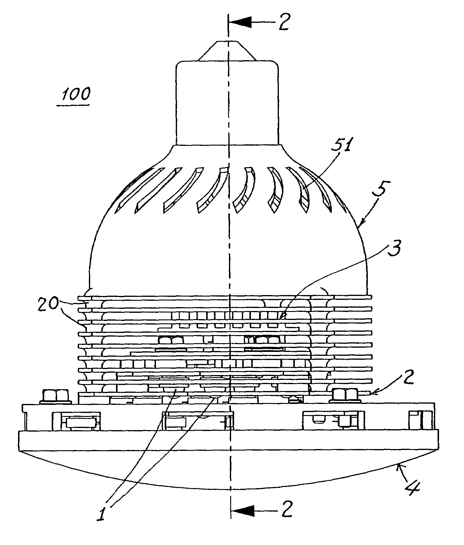
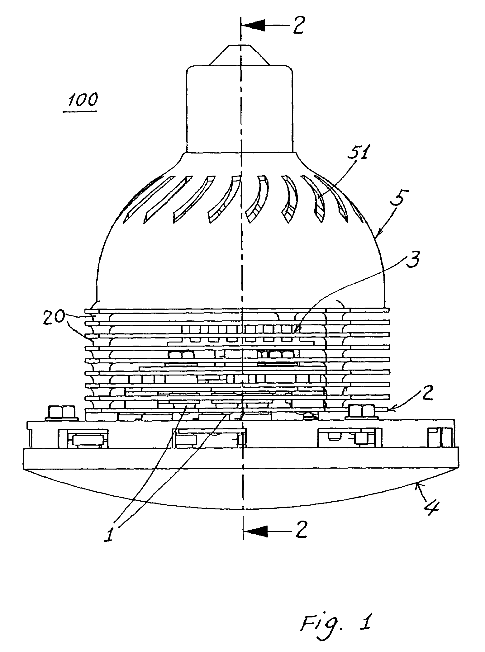
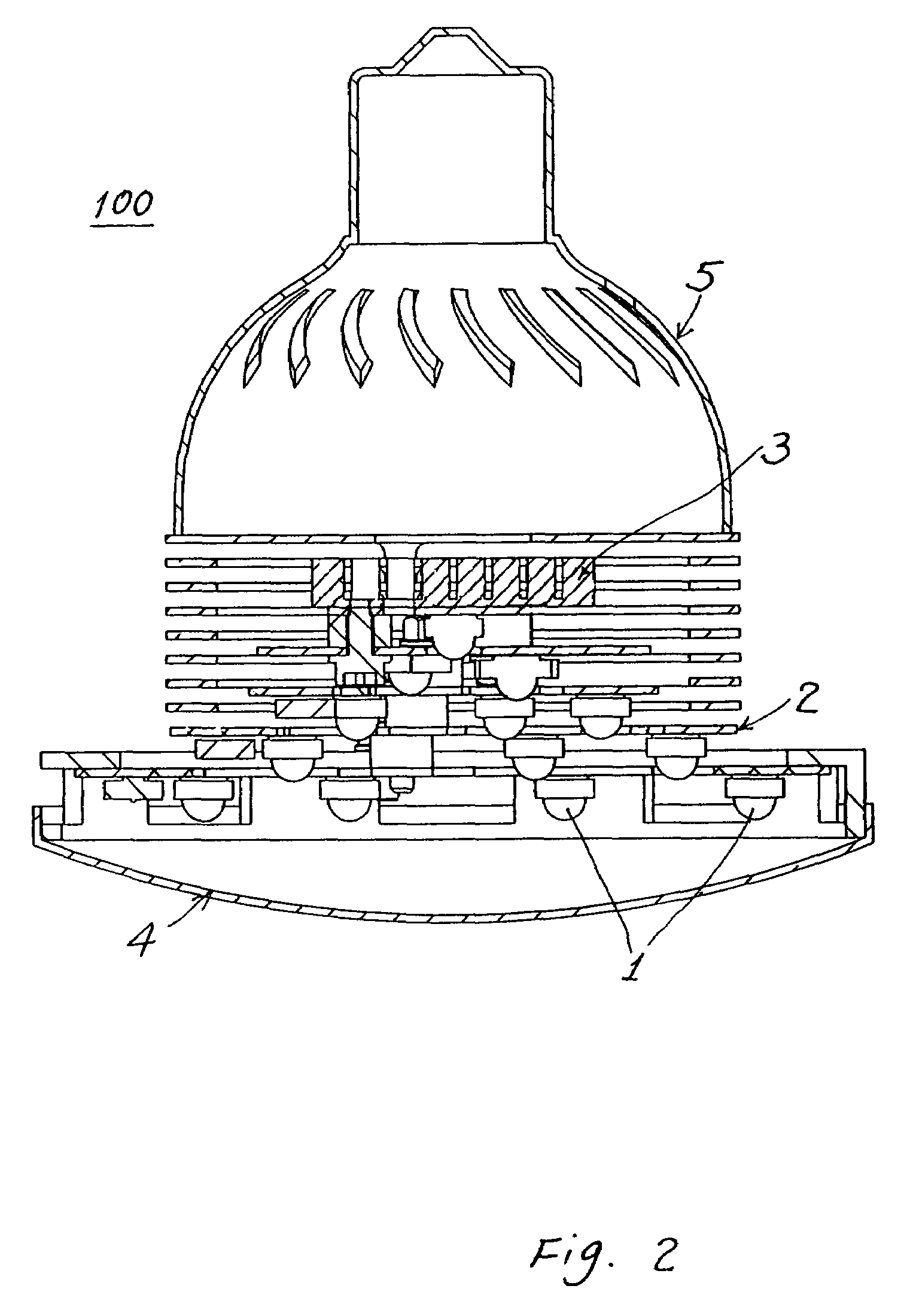
[0020]As shown in FIGS. 1˜5, a LED lamp (or lighting fixture) 100 of the present invention comprises: a plurality of light-emitting diodes or LEDs 1; a plurality of substrates 2, 2a˜2d juxtapositionally formed as a multiple-layer structure; each substrate 2, 2a˜2d having at least a light emitting diode or LED 1 mounted thereon; and at least a heat-dissipating device 3 secured to one substrate of the plurality of substrates 2, 2a˜2d; a transparent cover (or lens cover) 4 mounted on a front portion or a light-output side of the LED lamp 100; and at least a lamp shade 5 mounted on a rear portion or inner portion of the LED lamp 100.

[0021]The light emitting diodes 1 may be secured or mounted on each substrate 2, 2a˜2d by individual LEDs, an annular array, a LED module, or any other array arrangements or lay-out, not limited in the present invention.

[0022]The number, shapes, mounting or assembly methods of the elements of the present invention are not limited.

[0023]The LEDs may be electr...


PUM


Abstract

A LED lamp includes: a plurality of substrates juxtapositionally formed as multiple layers, each substrate having a plurality of light emitting diodes (LEDs) mounted thereon, whereby upon generation of heat by the LEDs when lit up, each substrate will form as a heat-dissipating plate in-situ in order that the multiple-layer substrates will instantly effectively dissipate the heat produced from the LEDs of the lamp outwardly for preventing deterioration of the illumination quality of the LED lamp.

Description

BACKGROUND OF THE INVENTION[0001]Once a LED lamp having a plurality of light emitting diodes is lit up, the LEDs or LED module will rapidly increase their temperature to accumulate heat in the lamp. If the heat is not well dissipated, it may cause flicker and deteriorate the illumination quality of the LED lamp, thereby shortening the service life of the lamp.[0002]U.S. Pat. No. 6,793,374 disclosed a LED lamp having a gear column connected between a cap and substrates. The substrates are arranged as a polyhedron with planar surfaces. A fan is provided in the column for cooling the substrates and LEDs.[0003]However, such a prior art has the following drawbacks:[0004]1. The LED substrates are formed as a polyhedron, which is a closed “housing” to greatly accumulate the heat produced by LEDs in the column, being difficult to dissipate the heat satisfactorily.[0005]2. A fan (9) should be installed in the column for cooling the lamp, increasing the cost of installation, operation and mai...

Claims


Application Information

Patent Timeline
Patent Type & Authority Patents(United States)
IPC IPC(8): F21V29/00
CPCF21K9/13F21S8/086F21V29/004F21V29/83F21V29/71F21V29/763F21V29/767F21V29/773F21W2111/02F21Y2101/02F21Y2111/008F21V29/507F21V29/75Y10S362/80F21K9/23F21Y2115/10F21Y2107/60F21V29/51F21V29/74
Inventor KANG, SHUNG-WENCHIEN, KUN-CHENG
Owner TAMKANG UNIVERSITY
Why Eureka
Try Eureka