Medical appliance delivery apparatus and method of use

a technology of stent and device, which is applied in the field of medical devices, can solve the problems of not having a safety mechanism to prevent excessive deployment of stent, no conventional way of correcting errors short of removing stent, and generally not being able to realign with respect to stent, etc., and achieves the effect of convenient and repeatable delivery of stents

Inactive Publication Date: 2009-10-27
MERIT MEDICAL SYST INC
View PDF371 Cites 72 Cited by
  • Summary
  • Abstract
  • Description
  • Claims
  • Application Information

AI Technical Summary

Benefits of technology

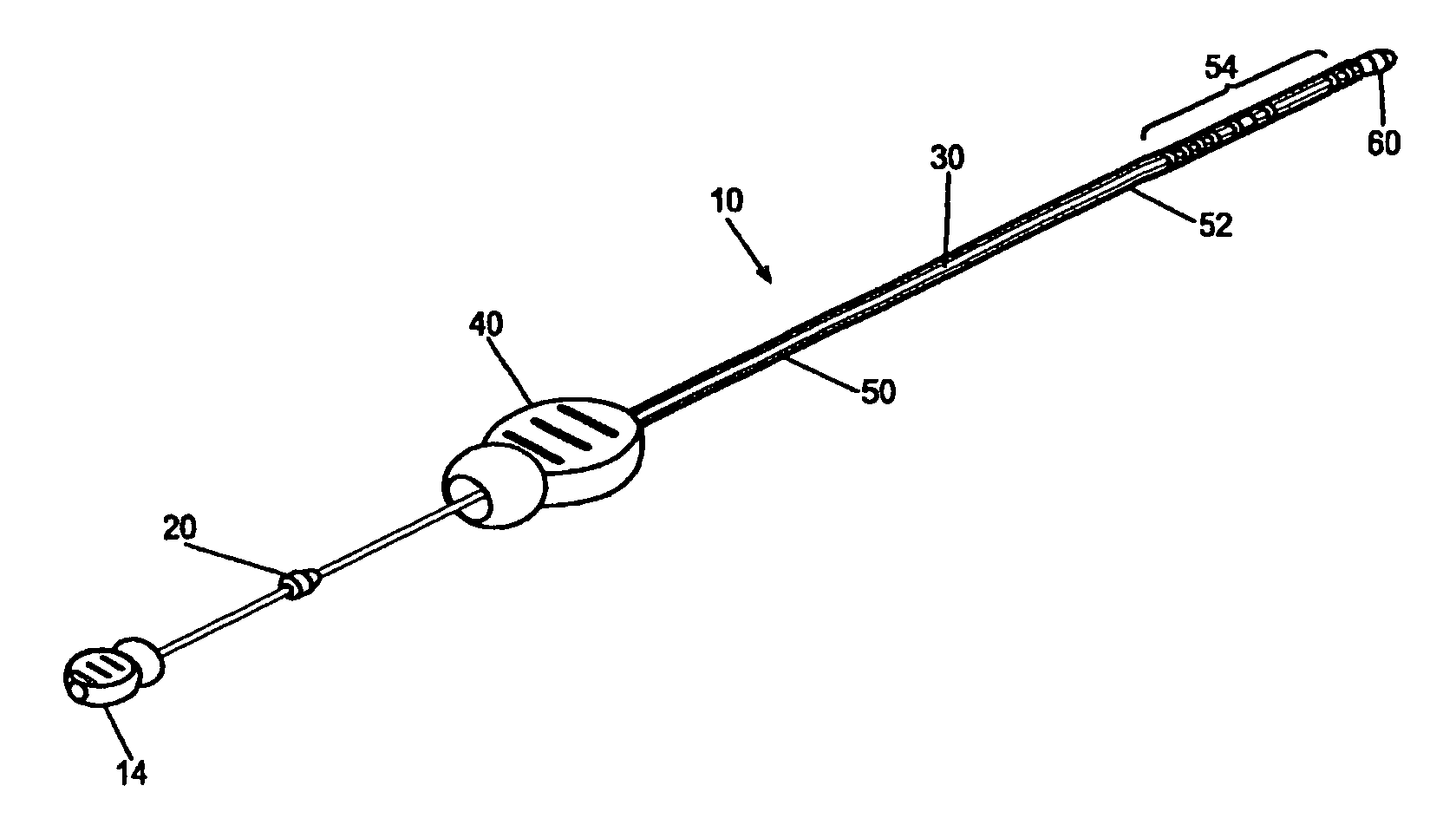
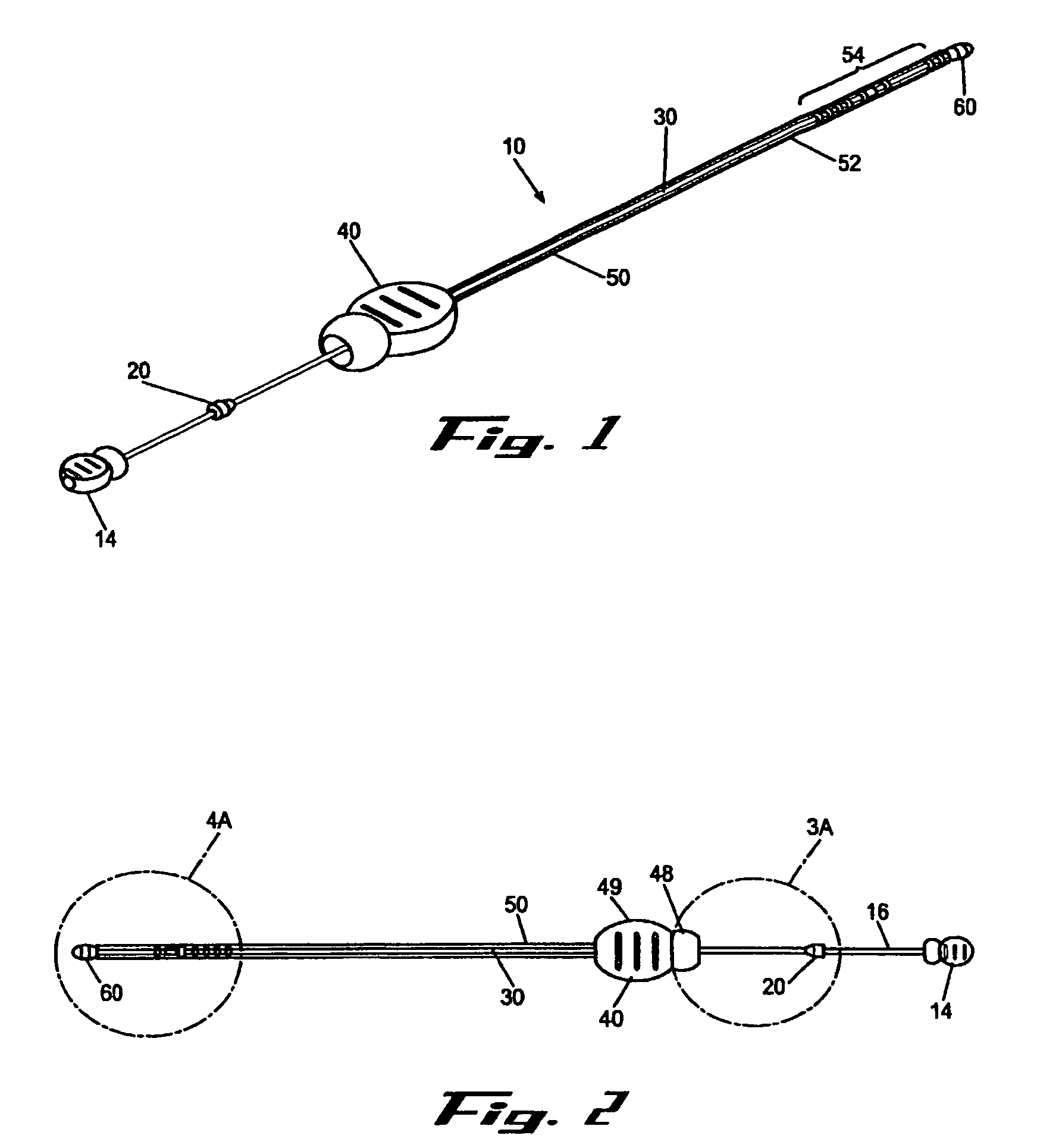
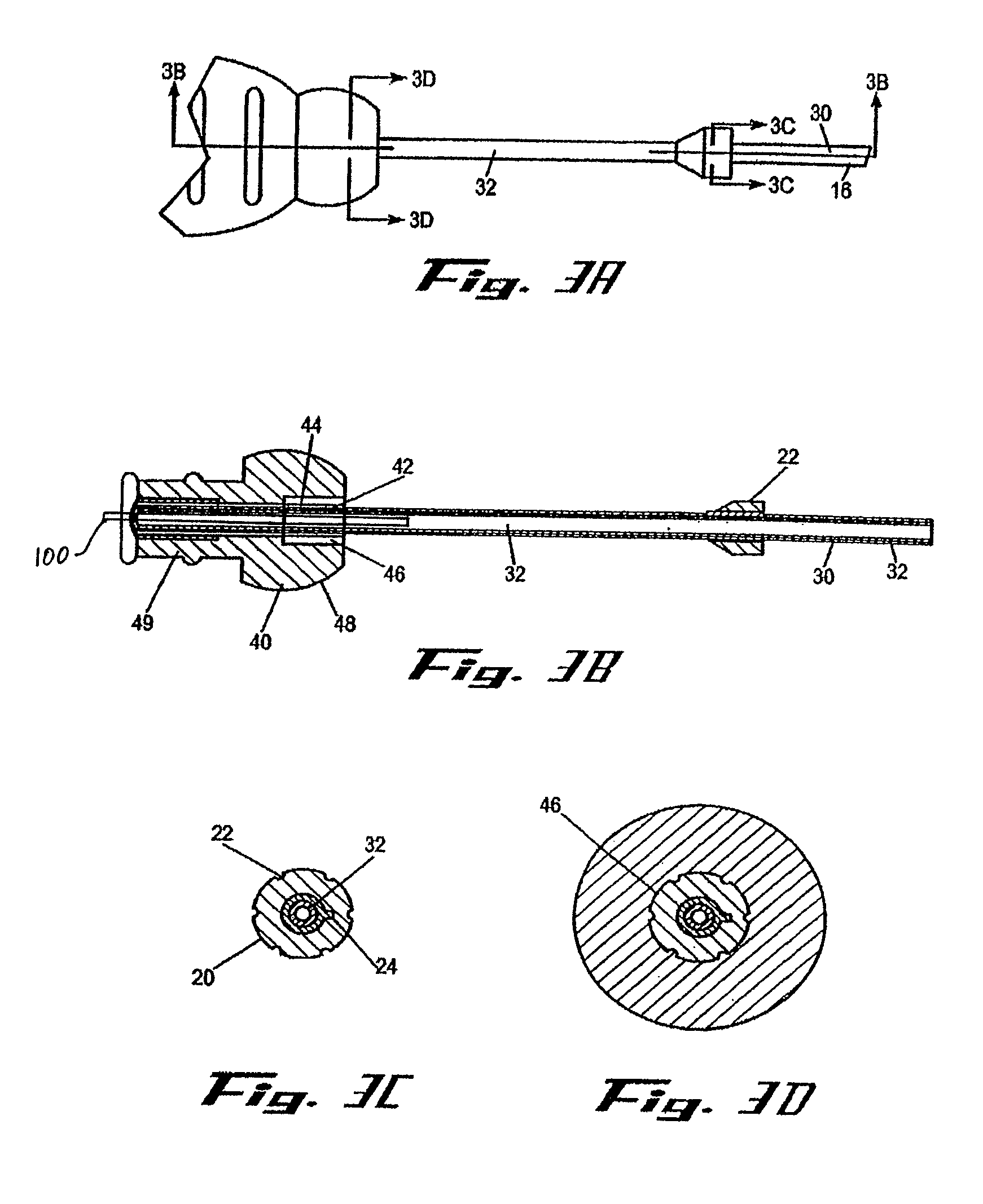
[0009]It is a principal objective of an exemplary stent deployment apparatus in accordance with the present invention to provide a device that can facilitate the precise delivery of stents in a safe and repeatable fashion. In the furtherance of this and other objectives, a preferred deployment apparatus allows the physician to concentrate on correct placement without having to estimate extent of deployment. In particular, in a preferred embodiment, the present deployment apparatus has a physical safety mechanism that limits deployment to the critical deployment point (i.e., ˜60%). The critical deployment point may range form 5% to 95% but is preferably about 60%. At this point, if the physician is satisfied with placement, she can engage the safety means to what we refer to as the Proceed Orientation (PO) and fully deploy the stent. It is preferred that when the safety mechanism is engaged to the PO, a physical twist and a possible audible indicator sounds to inform the physician that if she deploys the stent any further, she can no longer retract the stent beyond this point. Though the present stent and delivery system eliminates the need for repositioning, such safety features are still preferable. In a preferred embodiment, the slight audible indication is the sound of a tab or stop snapping to allow free deployment of the stent.
[0011]Yet another objective in accordance with the present invention is to provide a deployment apparatus having a distal tip designed to facilitate the clearance of obstructed lumen. In the furtherance of this and other objectives, the exemplary distal tips are configured to comfortably guide the deployment apparatus through a diseased or occluded lumen so that the stent can be delivered in the most beneficial location.
[0012]Still another objective of a preferred deployment apparatus in accordance with the present invention is to provide a distal tip that facilitates the removal of the deployment apparatus once the stent is radially expanded. In the furtherance of this and other objectives, the distal tip is designed to clear the stent during removal, in the event the stent does not adequately expand to preset dimensions. In a preferred embodiment, removal is facilitated by providing a distal tip that has a substantially bidirectional conic shape. This allows for the removal of the present deployment apparatus, while conventional deployment apparatuses would be stuck in the patient until some invasive procedure was performed to remove it and the defective stent. This results from the fact that conventional deployment apparatus designs rely exclusively on dimensional mismatching between the distal tip and the radially expanded stent to ensure proper removal of the deployment apparatus. As a function of the design of the present invention, the compressed stent is adequately retained in place and does not prematurely creep up the proximally facing conic end of the distal tip and prematurely deploy.
[0014]In addition to the above objectives, an exemplary stent deployment apparatus preferably has one or more of the following characteristics: (1) applicable for various interventional applications such as addressing stenosis; (2) biocompatible; (3) compliant with radially expanding stents; (4) capable of distal or proximal stent release; (5) smooth and clean outer surface; (6) length of the device variable according to the insertion procedure to be employed; (7) outer dimension as small as possible (depends on the diameter of crimped stent); (8) dimensions of the device must offer enough space for the crimped stent; (9) radiopaque markers, preferably on the inner tubular member, to indicate proximal and distal ends of the stent; (10) sufficient flexibility to adapt to luminal curvatures without loss of ability to push or pull; (11) low friction between the inner tubular member and outer tubular member; (12) sufficient resistance to kinking; (13) good deployment, ability to reposition partially deployed stent; (14) added with a scale to observe the stent position during the insertion procedure; (15) insertion procedure should require low force; or (16) sufficiently economical to manufacture so as to make the deployment apparatus disposable.

Problems solved by technology

Unfortunately, guidance of the stent has substantially remained a function of physician skill resulting from substantial practice.
If after full deployment of the stent, the physician discovers the stent has been implanted incorrectly, there is no conventional way of correcting the error short of removing the stent.
In particular, as a rule of thumb, once the exterior catheter, of conventional delivery devices, has been retracted beyond 60%, it generally cannot be realigned with respect to the stent.
Conventional stent delivery devices, however, do not have any safety mechanism to prevent excessive deployment of a misaligned stent.
In fact, conventional delivery devices require the physician to estimate extent of deployment, which results in either overly conservative or excessive deployment—both of which leads to stent misplacement.
An additional limitation of conventional stent delivery devices is the distal tip of conventional stent delivery devices are not adequately designed to (1) facilitate the clearance of obstructed lumen, or (2) facilitate the removal of the delivery device once the stent is radially expanded.
In particular, most distal tips are not configured to comfortably guide the delivery device through a diseased or occluded lumen so that the stent can be delivered in the most beneficial location.
Moreover, once the stent is radially expanded conventional designs rely exclusively on dimensional mismatching to ensure proper removal of the delivery device.
In the event the stent does not adequately expand to preset dimensions, a conventional delivery device would be stuck in the patient until some invasive procedure is performed to remove it and the defective stent.

Method used


Image

  • Medical appliance delivery apparatus and method of use
  • Medical appliance delivery apparatus and method of use
  • Medical appliance delivery apparatus and method of use

Examples


Embodiment Construction

[0009]It is a principal objective of an exemplary stent deployment apparatus in accordance with the present invention to provide a device that can facilitate the precise delivery of stents in a safe and repeatable fashion. In the furtherance of this and other objectives, a preferred deployment apparatus allows the physician to concentrate on correct placement without having to estimate extent of deployment. In particular, in a preferred embodiment, the present deployment apparatus has a physical safety mechanism that limits deployment to the critical deployment point (i.e., ˜60%). The critical deployment point may range form 5% to 95% but is preferably about 60%. At this point, if the physician is satisfied with placement, she can engage the safety means to what we refer to as the Proceed Orientation (PO) and fully deploy the stent. It is preferred that when the safety mechanism is engaged to the PO, a physical twist and a possible audible indicator sounds to inform the physician th...


PUM


Abstract

The present invention, in an exemplary embodiment, provides a stent deployment apparatus comprising excellent safety and stent placement and deployment features. An exemplary stent deployment apparatus in accordance with the present invention can facilitate the precise delivery of stents in a safe and repeatable fashion. In particular, a preferred deployment apparatus allows the physician to concentrate on correct placement without having to estimate extent of deployment by providing a physical safety mechanism that limits deployment to the critical deployment point. Moreover, to exceed this threshold, an audible and / or tactile indicator informs the physician that she can no longer retract the stent beyond this point. The stent deployment apparatus guidewire may also be extended rather than retracting the outer catheter to deliver the stent. Moreover, the distal tip is designed to comfortably guide the deployment apparatus through a diseased or occluded lumen so that the stent can be delivered in the most beneficial location. Additionally, the distal tip facilitates the removal of the deployment apparatus even if a defective stent is only partially radially expanded. In alternative embodiments, the stent deployment apparatus allows for the insertion of an optical scope to facilitate stent delivery.

Description

CROSS-REFERENCE TO RELATED APPLICATIONS[0001]This application is a continuation of U.S. application Ser. No. 10 / 281,429, filed Oct. 26, 2002, now abandoned which is hereby incorporated herein in its entirety by reference.FIELD OF THE INVENTION[0002]The present invention relates generally to medical devices directed to the prevention of nonvascular vessel or passageway occlusion, and more particularly to stent deployment apparatuses and methods for utilizing these devices in the treatment of both benign and malignant conditions.BACKGROUND OF THE INVENTION[0003]Stents are devices that are inserted into a vessel or passage to keep the lumen open and prevent closure due to a stricture, external compression, or internal obstruction. In particular, stents are commonly used to keep blood vessels open in the coronary arteries and they are frequently inserted into the ureters to maintain drainage from the kidneys, the bile duct for pancreatic cancer or cholangiocarcinoma or the esophagus for...

Claims


Application Information

Patent Timeline
Patent Type & Authority Patents(United States)
IPC IPC(8): A61F2/06A61B17/00A61BA61F2/84A61F11/00
CPCA61F2/95A61F2250/008A61F2002/9517A61F2/966A61F2/9517
Inventor JOHNSON, LIANN MSHERBURNE, PAUL SHECK, ALICIA F.SMELSER, RICCI D.MANGIARDI, ERIC K
Owner MERIT MEDICAL SYST INC
Why Eureka
Try Eureka