

Medical appliance optical delivery and deployment apparatus and method
a technology for optical delivery and medical appliances, applied in the field of stent deployment, can solve the problems of affecting patient ventilation, not giving adequate visual certainty, tissue luminal inflammation and tissue granulation, etc., and achieve the effect of convenient and safe delivery of stents
- Summary
- Abstract
- Description
- Claims
- Application Information
AI Technical Summary
Benefits of technology
Problems solved by technology
Method used
Image

Examples
Embodiment Construction
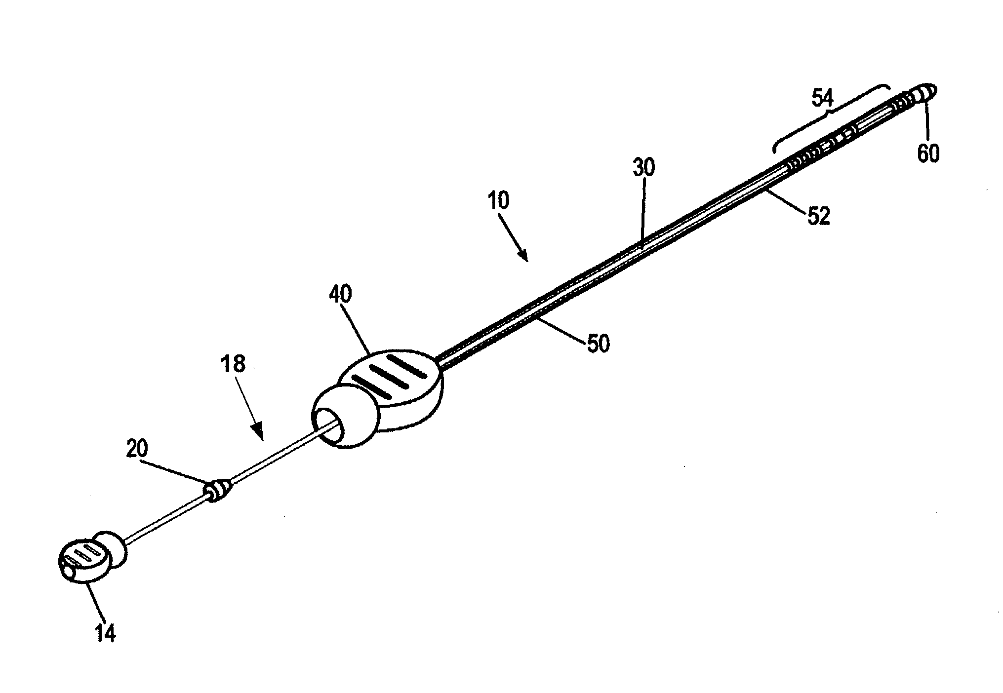
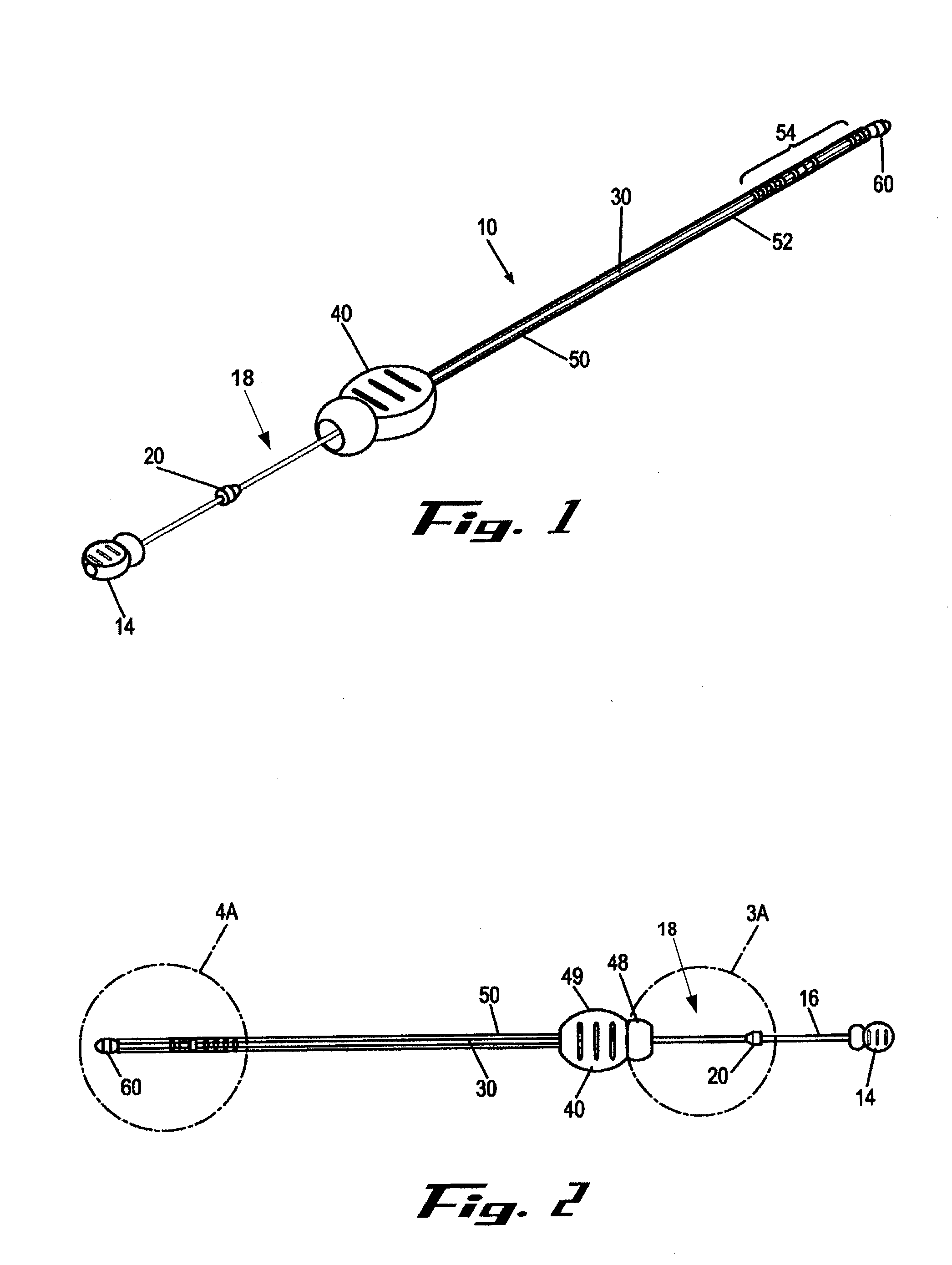
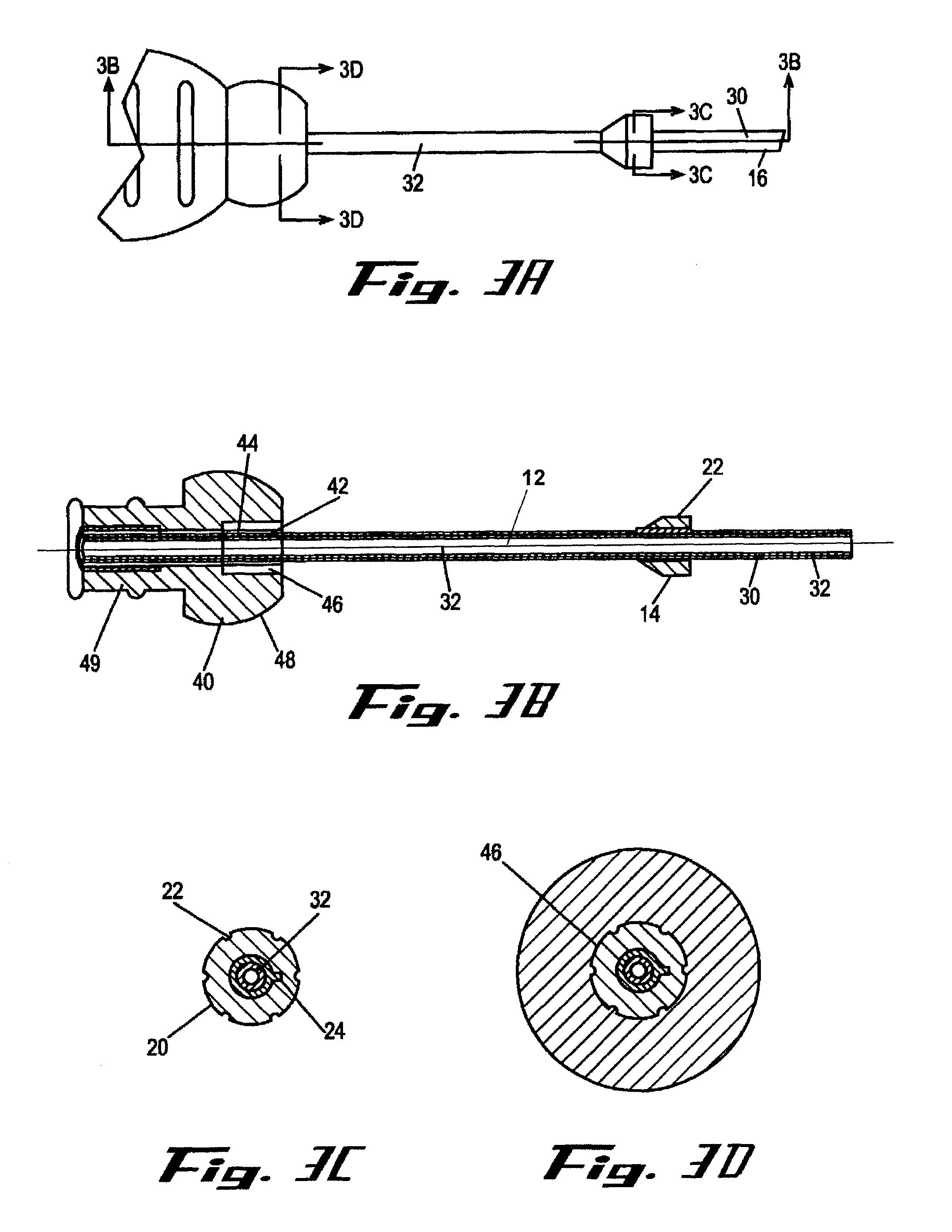
[0010]It is a principal objective of an exemplary stent deployment apparatus in accordance with the present invention to provide a device that can facilitate the precise delivery of stents in a safe and repeatable fashion. In the furtherance of this and other objectives, a preferred deployment apparatus allows the physician to concentrate on correct placement without having to estimate extent of deployment. In particular, in a preferred embodiment, the present deployment apparatus has a physical safety mechanism that limits deployment to the critical deployment point (i.e., ˜60%). The critical deployment point may range from 5% to 95% but is preferably about 60%. At this point, if the physician is satisfied with placement, she can engage the safety means to what we refer to as the Proceed Orientation (PO) and fully deploy the stent. It is preferred that when the safety mechanism is engaged to the PO, a physical twist and a possible audible indicator sounds to inform the physician th...
PUM
 Abstract
Description
Claims
Application Information