Substrate processing apparatus and method

a processing apparatus and substrate technology, applied in the direction of photomechanical treatment, cleaning using liquids, instruments, etc., to achieve the effect of easy splashing at the chuck pin

Active Publication Date: 2009-10-27
DAINIPPON SCREEN MTG CO LTD
View PDF27 Cites 12 Cited by
  • Summary
  • Abstract
  • Description
  • Claims
  • Application Information

AI Technical Summary

Benefits of technology

[0008]However, the approach that the chuck pins are disposed as a holding member near the outer edge of a substrate and the substrate is positioned in the horizontal direction and supported may cause a processing liquid moving outward in the diameter direction on the surface of the substrate during processing to directly hit and jump at the chuck pins and to adhere to the surface of the substrate again without getting discharged to outside the substrate. In addition, as the rotary base member rotates, the chuck pins disposed upward to the rotary base member disturbs air flows around the edge surface of the substrate. In consequence, the mist-like processing liquid splashing around during processing may suck in and enter the space which is created between the substrate and the blocking member (or the rotary base member) and adhere to the surface of the substrate again. Further, while a chuck for the substrate may be opened and closed (i.e., the substrate may be released) during processing for the purpose of processing a holding section on the substrate where the chuck pins holds the substrate, in this case, the processing liquid moving outward in the diameter direction over the substrate in particular can easily splash at the chuck pins.
[0009]The present invention has been made in light of the problems above. Accordingly, the object of the invention is to effectively prevent re-adhering of a processing liquid to the surfaces of a substrate in a substrate processing apparatus and method in which a predetermined processing is performed on the substrate by supplying the processing liquid to the substrate while rotating the substrate.

Problems solved by technology

However, the approach that the chuck pins are disposed as a holding member near the outer edge of a substrate and the substrate is positioned in the horizontal direction and supported may cause a processing liquid moving outward in the diameter direction on the surface of the substrate during processing to directly hit and jump at the chuck pins and to adhere to the surface of the substrate again without getting discharged to outside the substrate.
In addition, as the rotary base member rotates, the chuck pins disposed upward to the rotary base member disturbs air flows around the edge surface of the substrate.

Method used


Image

  • Substrate processing apparatus and method
  • Substrate processing apparatus and method
  • Substrate processing apparatus and method

Examples


first embodiment

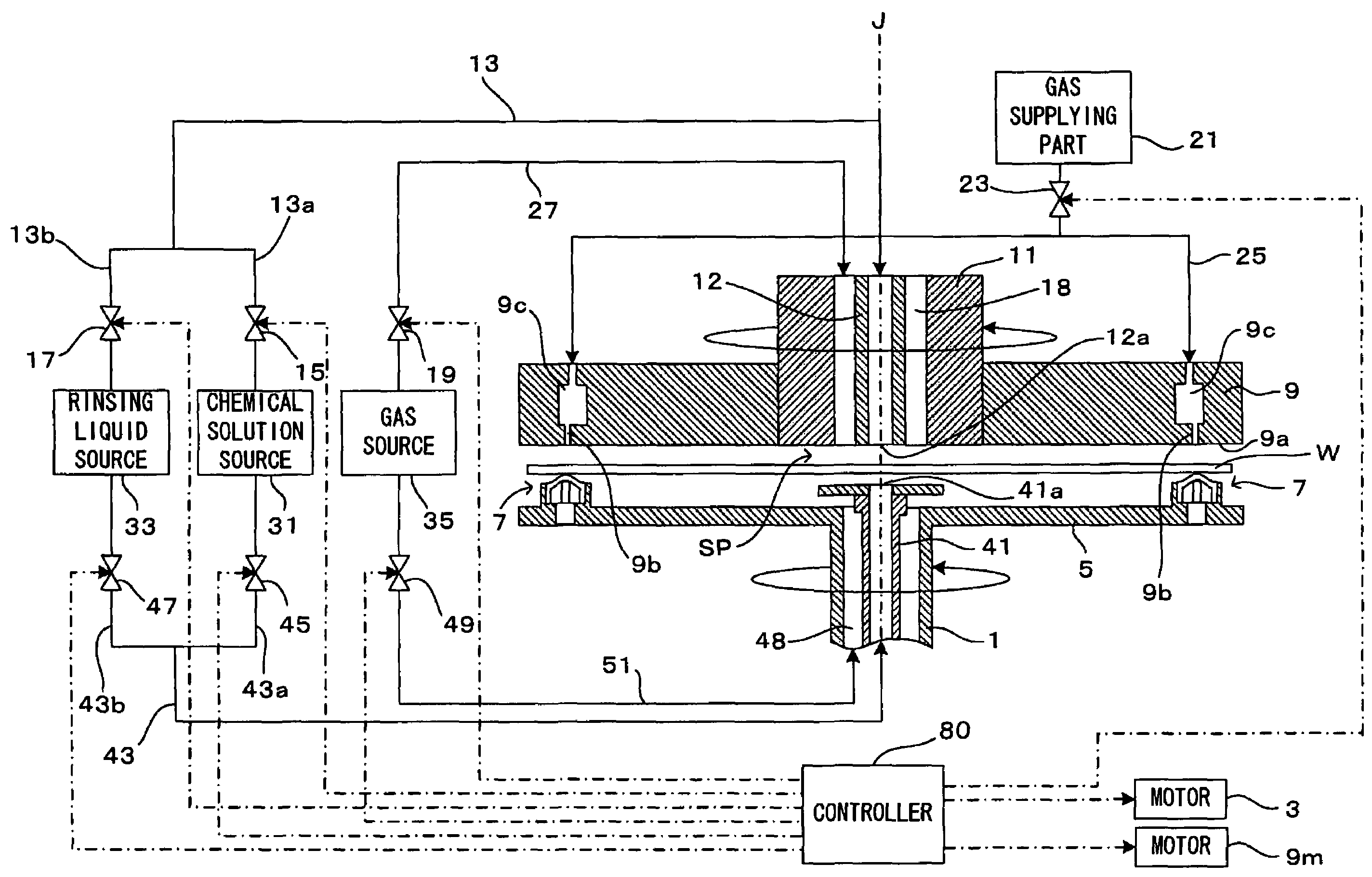
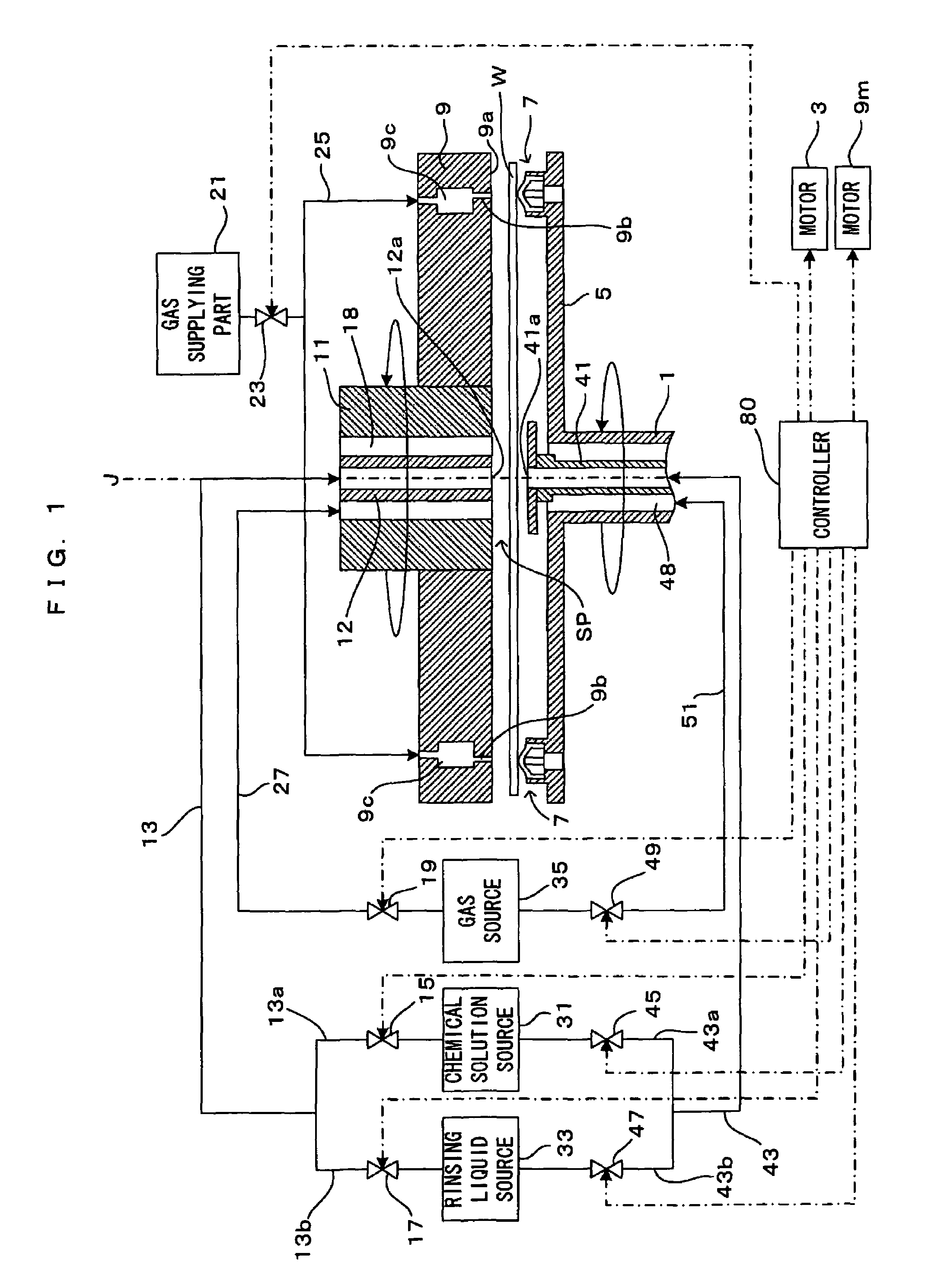
[0026]FIG. 1 is a drawing which shows a first embodiment of a substrate processing apparatus according to the present invention. This substrate processing apparatus is an apparatus in which a chemical solution of a chemical substance, an organic solvent or the like and a rinsing liquid which may be pure water or DIW (hereinafter also referred to as “processing liquid(s)”) are supplied to the surfaces of a substrate W such as a semiconductor wafer, and spin drying is executed after chemical processing and rinsing of the substrate W. In this substrate processing apparatus, the bottom surface of the substrate W can be processed while supplying the processing liquid to the bottom surface of the substrate W, and after supplied to the bottom surface of the substrate W, the processing liquid moves from the bottom surface of the substrate W to the edge surface of the substrate W and circles over to the top surface (a device-seating surface) of the substrate W, so that the top rim portion of...

second embodiment

[0063]FIG. 6 is a drawing which shows a second embodiment of the substrate processing apparatus according to the present invention. FIG. 7 is a plan view of the substrate processing apparatus which is shown in FIG. 6. A major difference of the second embodiment from the first embodiment is that a processing liquid nozzle 6 is additionally disposed at which the processing liquid is supplied to the top rim portion of the substrate W and that because of the processing liquid nozzle 6 which is additionally disposed, the structure of the atmosphere blocker plate 90 is modified partially. The second embodiment is otherwise basically similar in structure to the first embodiment. Hence, as for a condition for rotating the substrate W while pressing the substrate W against the supports 7 and holding the substrate W at the spin base 5, when the parameter range described in relation to the first embodiment are met, stable processing is realized without causing slipping of the substrate W. In t...

third embodiment

[0077]FIG. 10 is a drawing which shows a third embodiment of the substrate processing apparatus according to the present invention. FIG. 11 is a partial cross sectional view of the substrate processing apparatus shown in FIG. 10. While being similar to the second embodiment in that the processing liquid nozzle is additionally disposed at which the processing liquid is supplied to the top rim portion of the substrate W, the third embodiment is different from the second embodiment in that the atmosphere blocker plate 90 can not rotate while the processing liquid is supplied to the top surface of the substrate W in the second embodiment, the atmosphere blocker plate can rotate in the third embodiment. Except for this difference which requires a partial modification of the structure of the atmosphere blocker plate, the structure according to the third embodiment is basically similar to those according to the first and the second embodiments. Hence, as for a condition for rotating the su...


PUM

PropertyMeasurementUnit
distanceaaaaaaaaaa
diameteraaaaaaaaaa
distanceaaaaaaaaaa

Abstract

In the vicinity of a rim portion of a spin base 5, a plurality of supports 7 which abut on a bottom rim portion of a substrate W and support the substrate W are formed projecting toward above from the spin base 5. The substrate W is supported horizontally by the plurality of supports 7, with a predetermined distance ensured from the spin base 5 which opposes the bottom surface of the substrate W. Into the space which is created between the top surface of the substrate W and an opposing surface 9a of an atmosphere blocker plate 9, inert gas is ejected from a plurality of gas ejection outlets 9b which are formed in the opposing surface 9a. The inert gas thus supplied to the top surface of the substrate W presses the substrate W against the supports 7 and the substrate W is held at the spin base 5.

Description

CROSS REFERENCE TO RELATED APPLICATION[0001]The disclosure of Japanese Patent Applications enumerated below including specification, drawings and claims is incorporated herein by reference in its entirety:[0002]No. 2004-175730 filed Jun. 14, 2004; and[0003]No. 2004-362178 filed Dec. 15, 2004.BACKGROUND OF THE INVENTION[0004]1. Field of the Invention[0005]The invention relates to a substrate processing apparatus which performs processing such as cleaning on various types of substrates such as semiconductor wafers, glass substrates for photomask, glass substrates for liquid crystal display, glass substrates for plasma display and optical disk substrates by supplying a processing liquid to these substrates.[0006]2. Description of the Related Art[0007]Conventional substrate processing apparatuses of this type include a substrate processing apparatus in which a substrate such as a semiconductor wafer is supported on a disk-shaped rotary base member which is supported such that the rotary...

Claims


Application Information

Patent Timeline
Patent Type & Authority Patents(United States)
IPC IPC(8): B08B3/02B05D3/12B08B11/02G11B7/26H01L21/00H01L21/687
CPCB08B3/02B08B11/02H01L21/6875H01L21/67051H01L21/6708G11B7/266G03F1/82Y10S134/902
Inventor MIYA, KATSUHIKOANDO, KOJI
Owner DAINIPPON SCREEN MTG CO LTD
Why Eureka
Try Eureka