Tunnel construction equipment

A tunnel construction and equipment technology, applied in tunnels, tunnel linings, mining equipment, etc., can solve problems such as easy splashing of concrete mixture, increased impact force of valves, deformation of closed valves, etc., to avoid deformation, reduce impact force, and prevent impact Effect

Active Publication Date: 2020-09-29
湖南启力隧道机械有限公司
View PDF5 Cites 1 Cited by
  • Summary
  • Abstract
  • Description
  • Claims
  • Application Information

AI Technical Summary

Problems solved by technology

[0002] Shotcrete machine for tunnel construction. Wet shotcrete machine is used for tunnel support. Concrete pump is used to transport concrete mixture and sprayed out through nozzle. The concrete mixture of the sprayer has a lot of water and strong fluidity. Closing the valve after the spraying stops can easily make the concrete mixture form a rebound force and impact the interior at the same speed, making the concrete mixture of the mixer easy to splash and The highly fluid concrete mixture increases the impact force on valve closure, which can easily lead to excessive impact and deformation of the closed valve

Method used


Image

  • Tunnel construction equipment
  • Tunnel construction equipment
  • Tunnel construction equipment

Examples


Embodiment 1

[0023] like Figure 1-Figure 5 Shown:

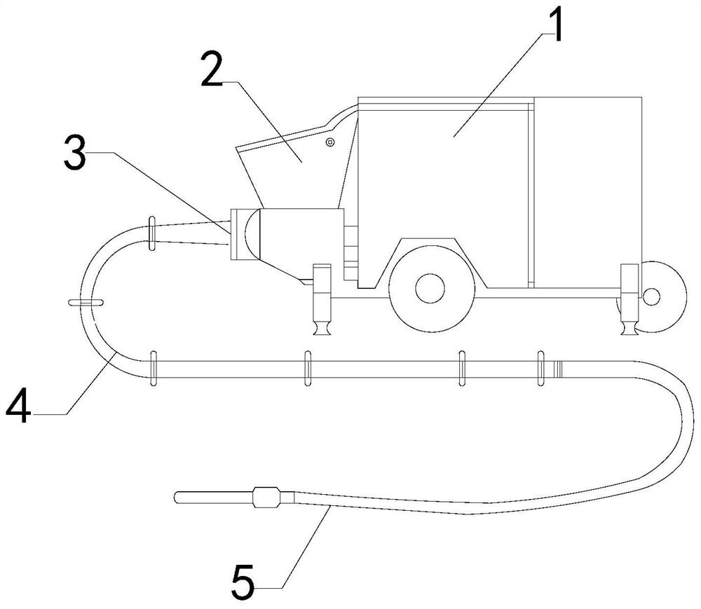
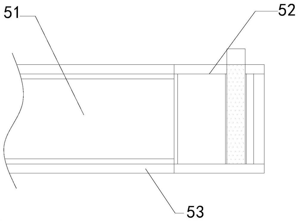
[0024] The present invention is a kind of tunnel construction equipment, its structure comprises motorized box 1, agitator 2, connecting pipe 3, transfer pipe 4, nozzle mechanism 5, described agitator 2 is installed on the left side of motorized box 1, and described connecting pipe 3 Connected to the lower end of the agitator 2, the transfer pipe 4 is embedded on the outside of the connecting pipe 3, the nozzle mechanism 5 is connected to the outer end of the transfer pipe 4, and the nozzle mechanism 5 is provided with a flow pipe 51 and a movable mechanism 52 , a smooth wall 53, the flow tube 51 is attached to the inside of the movable mechanism 52, the outside of the movable mechanism 52 is attached to the inside of the smooth wall 53, the flow tube 51 is connected to the left end of the transfer pipe 4, and the movable mechanism 52 The surface is equipped with a rotary switch.

[0025] Wherein, the movable mechanism 52 is provided w...

Embodiment 2

[0031] like Figure 6-Figure 7 Shown:

[0032] Wherein, the rotating mechanism w2 is provided with a magnetic block w21, a rotating shaft w22, a gap ring w23, and a rotating plate w24. The magnetic block w21 is attached to the outside of the rotating shaft w22, and the gap ring w23 is attached to the magnetic block w21. The outer side of the rotating plate w24 is fixed on the outer side of the gap ring w23, the rotating shaft w22 is located on the central axis of the valve w1, and the magnetic block w21 surrounds symmetrically around the rotating shaft w22.

[0033] Wherein, the rotating plate w24 is provided with a force bar b1 and a guide plate b2, the force bar b1 is attached to the surface of the guide plate b2, the side of the guide plate b2 is attached to the outer side of the gap ring w23, the The stress bar b1 has a triangular structure, and the guide plate b2 has a curved structure, which bears force on the concrete mixture and reduces resistance to the valve w1.

...


PUM


Abstract

The invention discloses tunnel construction equipment. The tunnel construction equipment structurally comprises a motor box, a stirrer, a connecting pipe, a connecting pipe and a spray head mechanism,the spray head mechanism is provided with a flowing pipe, a movable mechanism and a smooth wall, a concrete mixture flows in the flowing pipe, so that a spring rod is compressed, the impact force ona rotation mechanism is reduced, the deformation caused by excessive impact on a valve is avoided, the valve slides during impact, the inertia force of the concrete mixture is buffered, so that the impact force on the valve is reduced, when the concrete mixture impact a rotating mechanism in the rotation mechanism, a force strip is acted, so that a bent guide plate is stressed, an acting force angle of a rotating plate is consistent, the rotating plate rotates by taking a rotating shaft as a center point under the repulsive force of a magnetic block, the impact force is decelerated while rotating, the concrete mixture is prevented from forming rebound force, the internal impact is prevented, and the concrete mixture of the stirrer is prevented from splashing easily.

Description

technical field [0001] The invention relates to the field of tunnel construction, in particular to tunnel construction equipment. Background technique [0002] Shotcrete machine for tunnel construction. Wet shotcrete machine is used for tunnel support. Concrete pump is used to transport concrete mixture and sprayed out through nozzle. The concrete mixture of the sprayer has a lot of water and strong fluidity. Closing the valve after the spraying stops can easily make the concrete mixture form a rebound force and impact the interior at the same speed, making the concrete mixture of the mixer easy to splash and The highly fluid concrete mixture increases the impact force on valve closure, which easily leads to excessive impact and deformation of the closed valve. Contents of the invention [0003] The present invention is realized through the following technical solutions: its structure includes a motorized box, a stirrer, a connecting pipe, a transfer pipe, and a nozzle me...

Claims


Application Information

Patent Timeline
Patent Type & Authority Applications(China)
IPC IPC(8): E21D11/10F16F15/067
CPCE21D11/105F16F15/067
Inventor 杨泓
Owner 湖南启力隧道机械有限公司
Why Eureka
Try Eureka