
Full cone air assisted spray nozzle for continuous metal casting cooling

a technology of air assisted spray nozzles and continuous metal casting, which is applied in the direction of spray nozzles, liquid spraying apparatuses, chemistry apparatuses and processes, etc., can solve the problems of difficult and expensive manufacturing, difficult to reliably generate a full cone preatomized liquid spray discharge with a uniform distribution of liquid particles

Active Publication Date: 2009-11-03
SPRAYING SYST
View PDF20 Cites 17 Cited by
  • Summary
  • Abstract
  • Description
  • Claims
  • Application Information

AI Technical Summary

Benefits of technology

The solution effectively directs a full cone liquid spray pattern with uniform particle distribution, maintaining consistent spray angles over a wide pressure range and preventing clogging, enhancing cooling efficiency in continuous metal casting systems.

Problems solved by technology

Heretofore, however, it has been difficult to reliably generate a full cone preatomized liquid spray discharge with a uniform liquid particle distribution.
Such spray nozzles commonly require a whirl imparting vane which is relatively small in size, can be difficult and expensive to manufacture, and can be subject to clogging.

Method used


Image

  • Full cone air assisted spray nozzle for continuous metal casting cooling
  • Full cone air assisted spray nozzle for continuous metal casting cooling
  • Full cone air assisted spray nozzle for continuous metal casting cooling

Examples


Embodiment Construction

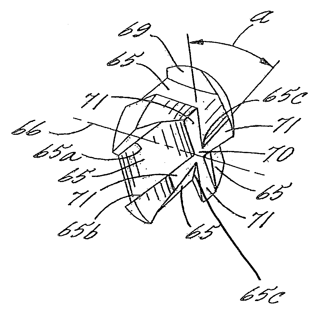
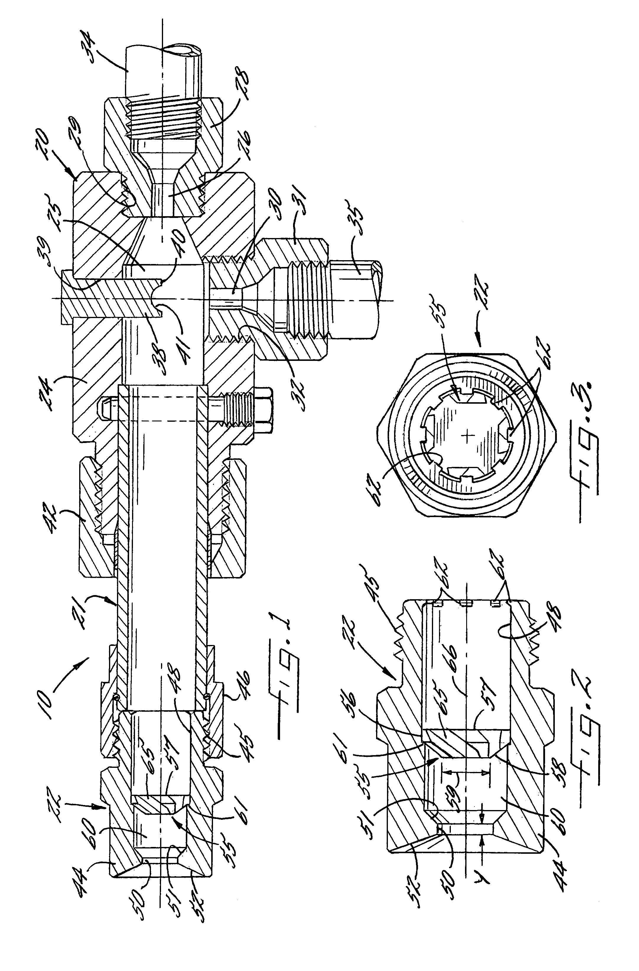
[0019]Referring now more particularly to FIG. 1 of the drawings, there is shown an illustrated air assisted liquid spray nozzle assembly 10 in accordance with the invention. It will be understood that a plurality of such spray nozzle assemblies may be utilized in a cooling system for a continuous metal casting apparatus, such as shown in the afore-mentioned U.S. Pat. No. 6,726,127, the disclosure of which is incorporated herein by reference.

[0020]The illustrated spray nozzle assembly 10 basically comprises a preliminary liquid atomizing head or section 20, an elongated tubular barrel 21 connected at its upstream end to the atomizing head 20, and a spray nozzle 22 connected to the downstream end of the barrel 21. The atomizing head 20 comprises a hollow body 24 having an elongated expansion chamber 25 extending axially thereof, a pressurized air inlet 26 defined by an orifice fitting 28 in threaded engagement in an axial bore 29 in an upstream end of the body 24, and a liquid coolant...


PUM


Abstract

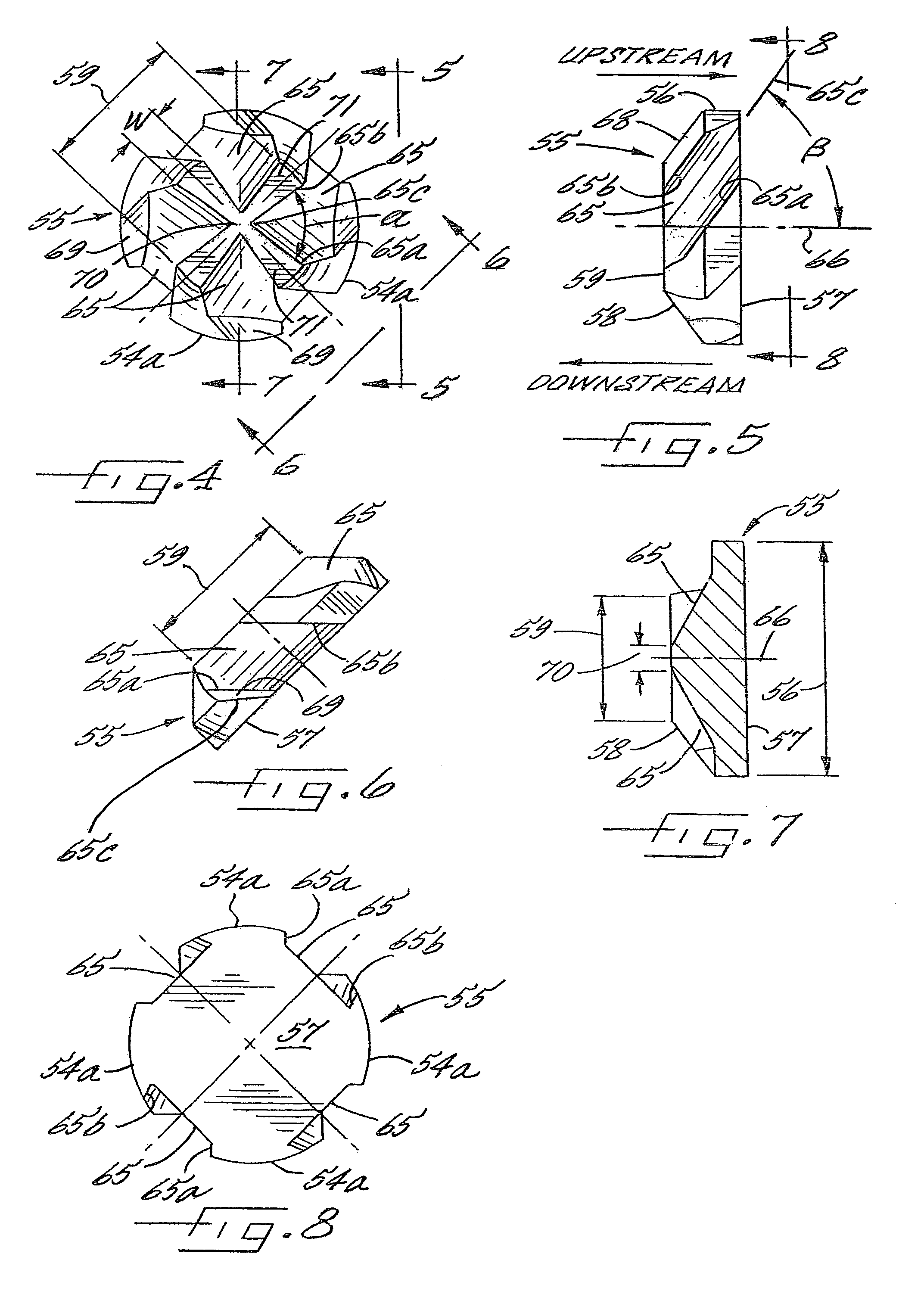
A full cone liquid spray nozzle is provided. The spray nozzle includes a nozzle body having a discharge orifice at a downstream end and an inlet at an upstream end for connection to a liquid supply. A liquid flow passageway extends through the nozzle body communicating between the inlet and the discharge orifice. A vane is disposed in the liquid flow passageway upstream of the discharge orifice. The vane has a plurality of V-shaped passageways therein. Each V-shaped passageway extends inward at an angle with respect to a longitudinal axis of the vane between an upstream face and downstream face of the vane. A whirl and mixing chamber defined by the liquid flow passageway is arranged between the vane and the discharge orifice.

Description

CROSS-REFERENCE TO RELATED APPLICATIONS[0001]This patent application claims the benefit of U.S. Provisional Patent Application No. 60 / 811,059, filed Jun. 5, 2006, which is incorporated by reference.FIELD OF THE INVENTION[0002]The present invention relates generally to pressurized air assisted spray nozzle assemblies, and more particularly, to an air assisted spray nozzle assembly adapted for spraying cooling liquid in continuous metal casting systems.BACKGROUND OF THE INVENTION[0003]Pressurized air assisted spray nozzle assemblies are known for spraying cooling liquids in continuous metal casting systems, such as disclosed in U.S. Pat. No. 6,726,127 assigned to the same assignee as the present application. Such spraying systems typically preatomize liquid and direct the liquid particles into a flat spray pattern. A plurality of such spray nozzles are aligned along the path of the movement of the continuous cast slab.[0004]In the continuous casting of billets, which are substantially...

Claims


Application Information

Patent Timeline
Patent Type & Authority Patents(United States)
IPC IPC(8): B05B1/34
CPCB05B1/3415B05B7/0416B05B7/10B01J4/004
Inventor PETERSON, LESLIHOFHERR, CHRISTY
Owner SPRAYING SYST
Learn More