Pneumatic seasoning system

a pneumatic seasoning and system technology, applied in the field of pneumatic seasoning system, can solve the problems of insufficient uniformity and adhesion of the topic, and achieve the effect of promoting superior adhesion and/or implantation, and promoting uniform particle distribution

Inactive Publication Date: 2010-11-09
FRITO LAY NORTH AMERICA INC
View PDF26 Cites 19 Cited by
  • Summary
  • Abstract
  • Description
  • Claims
  • Application Information

AI Technical Summary

Benefits of technology

[0011]In contrast, the primary differentiator for the pneumatic system of the present invention is the utilization of an in-line pneumatic vacuum nozzle to propel the seasoning onto the chip (or other food item) pieces. A specially designed spool-shaped nozzle introduces a swirling envelope of air around a dilute-phase pneumatic flow of seasoning to promote uniform particle distribution. A plurality of compressed-air ports arranged about the down-stream annulus of the nozzle provide the vacuum force used to create a turbulent swirling flow at the nozzle exit.
[0012]A prescribed number of nozzles are designed into the system to provide the proper product coverage and seasoning capacity. These nozzles are mechanically tied together via a line splitters and can be fed from a common volumetric or loss-in-weight feeder. The motive force and relatively high-velocity impact of the seasoning particles, which is on the order of roughly 30 fps, promotes superior adhesion and / or implantation to the product to be coated. Desirable adhesion and uniform distribution are possible without the use of a pre-seasoning oil spray.

Problems solved by technology

Due to the compounded variability of pre-seasoning oil application and seasoning application, topical uniformity and adhesion are not optimal.

Method used


Image

  • Pneumatic seasoning system
  • Pneumatic seasoning system
  • Pneumatic seasoning system

Examples


Embodiment Construction

[0097]In the following written description, and with reference to all the figures, the use of shared reference numerals and shared reference characters denotes the same or similar elements throughout the figures, unless otherwise stated. Note that while one or more embodiments are discussed in detail herein, such embodiments are not meant to be exclusive, and obvious and / or foreseeable variants are also encompassed by the present invention.

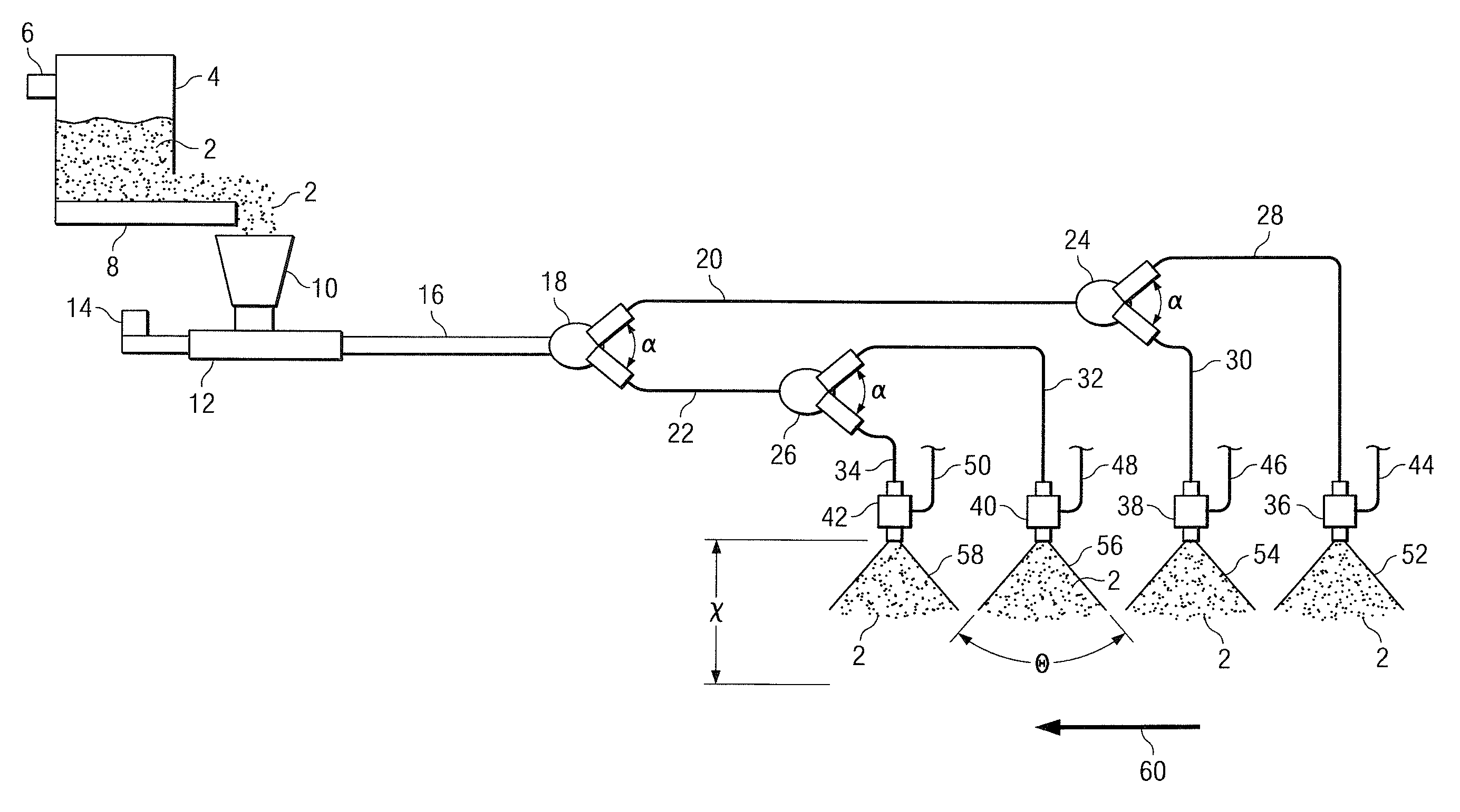
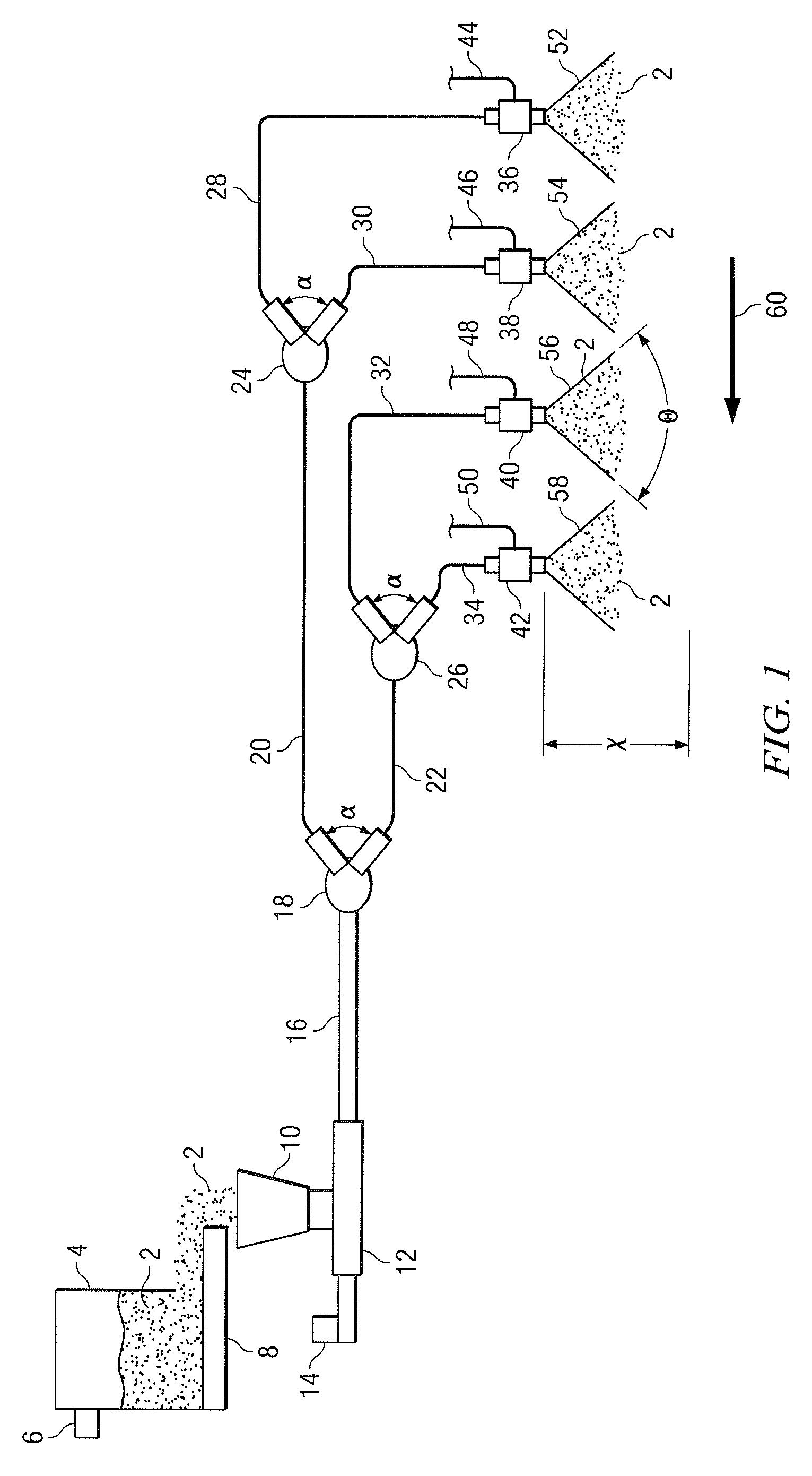
[0098]While pneumatic seasoning distributors have been used in conjunction with pre-seasoning oil sprays in the prior art, such systems tend to rely upon the adhesive characteristics of such pre-seasoning oil sprays: more specifically, the ability of such spray coatings to capture free-falling seasoning particles without becoming so adhesive or tacky as to cause undesirable product clumping, or in the other extreme, remaining so fluid as to drain off of the product. Rather than relying upon the use of pre-seasoning oil sprays, the present inventio...


PUM


Abstract

A pneumatic seasoning system and method utilizing a rotating drum for seasoning, a funnel-fed pneumatic eductor, line splitters, and a plurality of specially-designed swirl-inducing nozzle spools for inducing a broad and even seasoning plume. In a preferred embodiment, a pneumatic seasoning system transports seasoning from a seasoning hopper to food items within a rotating drum using a combination of an eductor and four in-line vacuum generators, which vacuum generators operate on compressed air. Each vacuum generator comprises a distributing nozzle roughly shaped like a collared spool, wherein compressed air is supplied to the annular region defined between the spool and its collar, and said compressed air exits through swirl ports distributed about the circumference of the spool exit. Each swirl port preferably has a pitch angle of 15° and a yaw angle of 15°.

Description

CROSS-REFERENCE TO RELATED APPLICATION[0001]None.BACKGROUND OF THE INVENTION[0002]1. Technical Field[0003]The present invention relates to a pneumatic seasoning system and method for evenly and consistently applying seasoning material to a food product, especially farinaceous-based food products. More specifically, the invention offers improved rotating drum-type seasoning by combining the use of a pneumatic eductor and one or more in-line vacuum-generating swirl-inducing nozzles.[0004]2. Description of Related Art[0005]Snack food products, particularly seasoned snacks chips, are eaten and enjoyed by consumers. For example, potato chips, tortilla chips, corn chips, and the like often include one or more seasonings added to the snack chips after cooking but prior to packaging. To season, snack chips are typically seasoned by sprinkling one or more seasonings onto the surface of the chip products. The surfaces of the chips after seasoning provide a desirable and interesting appearance...

Claims


Application Information

Patent Timeline
Patent Type & Authority Patents(United States)
IPC IPC(8): B05C19/04B05D1/12A23L7/157A23L19/18A23L27/00
CPCA21C15/002A23P1/081A23P1/083B05B7/10B05B7/1486B05B13/0257A23P20/10A23P20/13
Inventor GARRISON, WAYNESAMUELS, ROSS D.BARTLETT, GLYNN R.
Owner FRITO LAY NORTH AMERICA INC
Why Eureka
Try Eureka