Flight management process for an aircraft

a technology for managing process and aircraft, applied in the field of flight management process, can solve the problems of reducing speed and losing altitude of aircra

Inactive Publication Date: 2009-11-03
AIRBUS OPERATIONS (SAS)
View PDF13 Cites 25 Cited by
  • Summary
  • Abstract
  • Description
  • Claims
  • Application Information

AI Technical Summary

Benefits of technology

[0009]The purpose of this invention is to propose a landing process for an aircraft for which the noise level on the ground is minimized. Preferably, this process will permit a considerable reduction in the noise level on the ground for large aircraft as well as for smaller aircraft.
[0028]This invention suggests that in the course of the descent path of the aircraft towards a landing strip, it is proposed to the pilot to pass from the fully retracted position of the wing flaps to the first intermediate position of the wing flaps of the aircraft either at a first speed that coincides with the speed recommended to transition to the first intermediate position of the wing flaps, or at a speed, below the preceding one that permits reducing the aircraft noise.
[0029]This invention also suggests that in the course of the descent path of the aircraft towards a landing strip, it is proposed to the pilot to transition from the first intermediate position of the slats and wing flaps of the aircraft to the second intermediate position of these wing flaps or to a first speed that coincides with the recommended speed for going to the second intermediate position of the wing flaps, or to a speed, lower than the preceding one, that permits reducing the aircraft noise.

Problems solved by technology

Generally speaking, when landing, an aircraft loses altitude and reduces its speed to switch from cruising flight conditions to landing conditions.

Method used


Image

  • Flight management process for an aircraft
  • Flight management process for an aircraft
  • Flight management process for an aircraft

Examples


Embodiment Construction

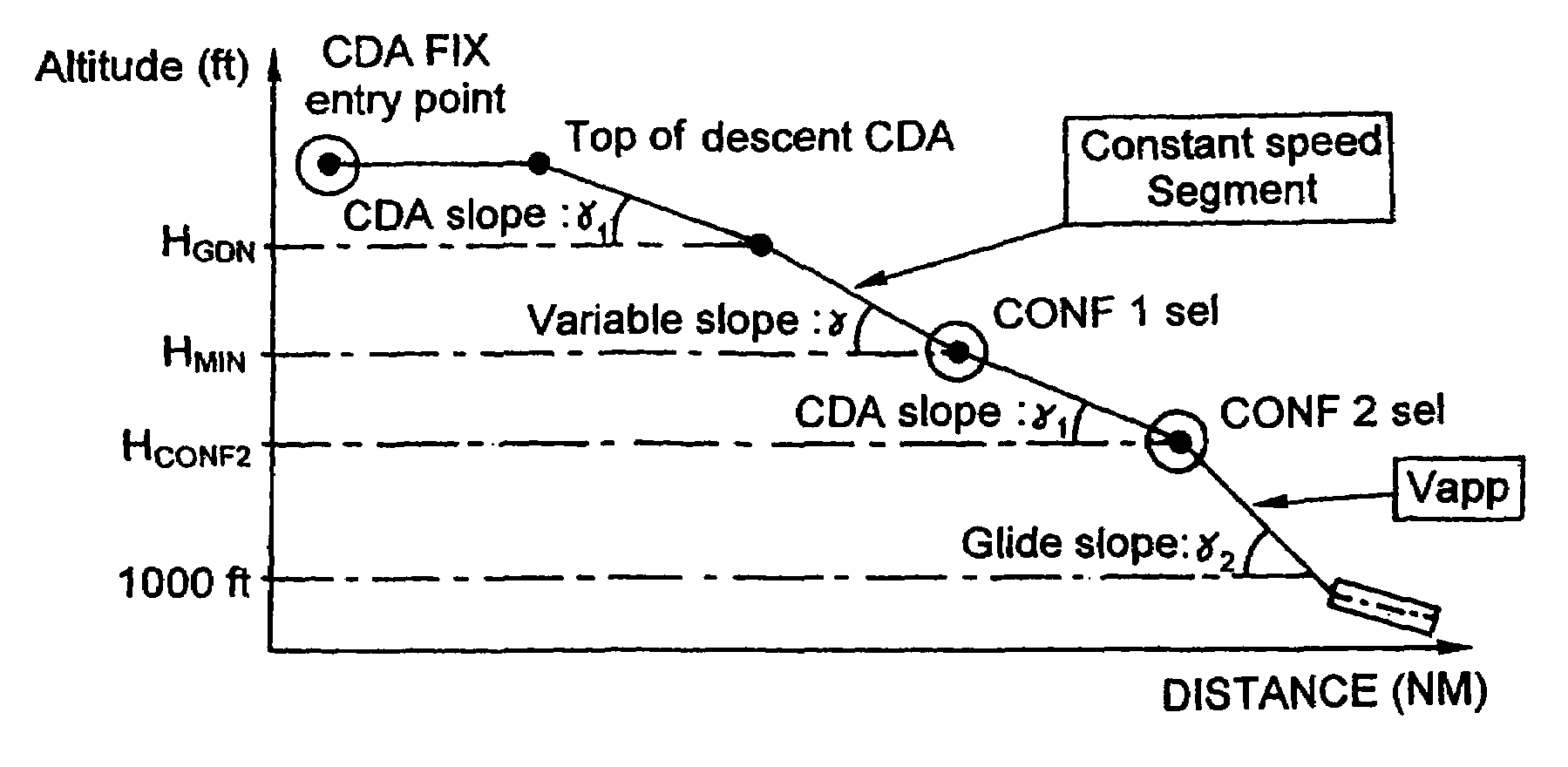
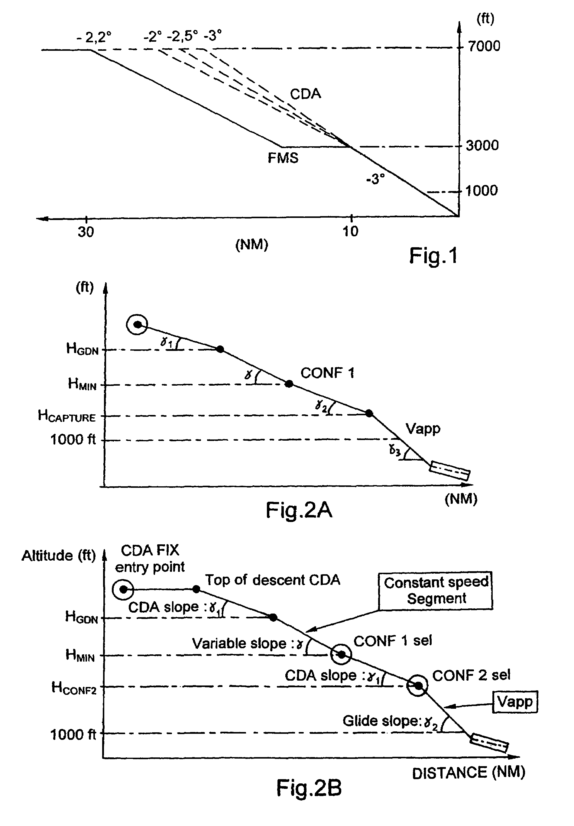
[0037]On the first figure, the landing process serving as reference is illustrated. This procedure is the one classically provided in a flight management system (FMS) of an aircraft.

[0038]In the description that follows, the altitude values shown are to be considered with respect to the terrain: such an altitude with respect to the terrain is sometimes also called “height”.

[0039]In the example selected, it is assumed that the aircraft initially is beginning its descent at a given speed and an altitude of 7000 feet (or 2133.6 meters). When this aircraft wants to land at an airport, it starts a first phase of descent during which, at constant speed, it moves from an altitude of 7000 feet to 3000 feet. Once this intermediate altitude of 3000 feet is reached, the aircraft slows down, then, progressively, extends its slats and wing flaps to the first intermediate position (here generally, the wing flaps remain in the retracted position) while continuing its deceleration phase. On the fig...


PUM


Abstract

A process wherein an aircraft starts from a cruising position by flying at a cruising speed to reach a position that intercepts the glide slope. The process can include the steps of decelerating from the begin descent speed and the begin descent altitude of the aircraft during a first descent phase with a first flight path angle until reaching a predetermined speed corresponding to an aircraft speed at which the aircraft flaps are extended for transitioning to a first intermediate position; following a second phase of descent at a considerably constant speed with a second flight path angle; and decelerating during a third phase of descent with a third flight path angle to reach the glide slope interception position. The aircraft slats and / or flaps adopt their first intermediate position considerably when transitioning from the second to the third phase of descent.

Description

CROSS-REFERENCE TO RELATED APPLICATIONS:[0001]This application claims priority to French Application No. 05 08212, filed Aug. 1, 2005, U.S. Provisional Application No. 60 / 644,533, filed Jan. 19, 2005 and U.S. Provisional Application No. 60 / 645,050, filed Jan. 21, 2005, the entire contents of which are hereby incorporated by reference.BACKGROUND OF THE INVENTION[0002]1. Field of the Invention[0003]The invention involves a flight management process, such as for landing an aircraft. The term “landing” includes the approach stage and the touching of the wheel on the landing strip or runway.[0004]2. Discussion of the Background[0005]Generally speaking, when landing, an aircraft loses altitude and reduces its speed to switch from cruising flight conditions to landing conditions. During its descent, the aircraft takes on various configurations. First of all, during flight at cruising speed, the outside surface of the aircraft is the smoothest possible. When it approaches the ground, severa...

Claims


Application Information

Patent Timeline
Patent Type & Authority Patents(United States)
IPC IPC(8): G05D1/12
CPCG05D1/0676G08G5/025Y02T50/84Y02T50/80
Inventor VAN BOVEN, MACHIEL
Owner AIRBUS OPERATIONS (SAS)
Why Eureka
Try Eureka