
Steam generator iron

a steam generator and iron technology, applied in the field of steam generator iron, can solve the problems achieve the effects of reducing the resistance to flow, reducing the noise generation at the transition, and reducing the noise level generated during use of the steam generator iron

Active Publication Date: 2016-06-14
VERSUNI HLDG BV
View PDF20 Cites 0 Cited by
  • Summary
  • Abstract
  • Description
  • Claims
  • Application Information

AI Technical Summary

Benefits of technology

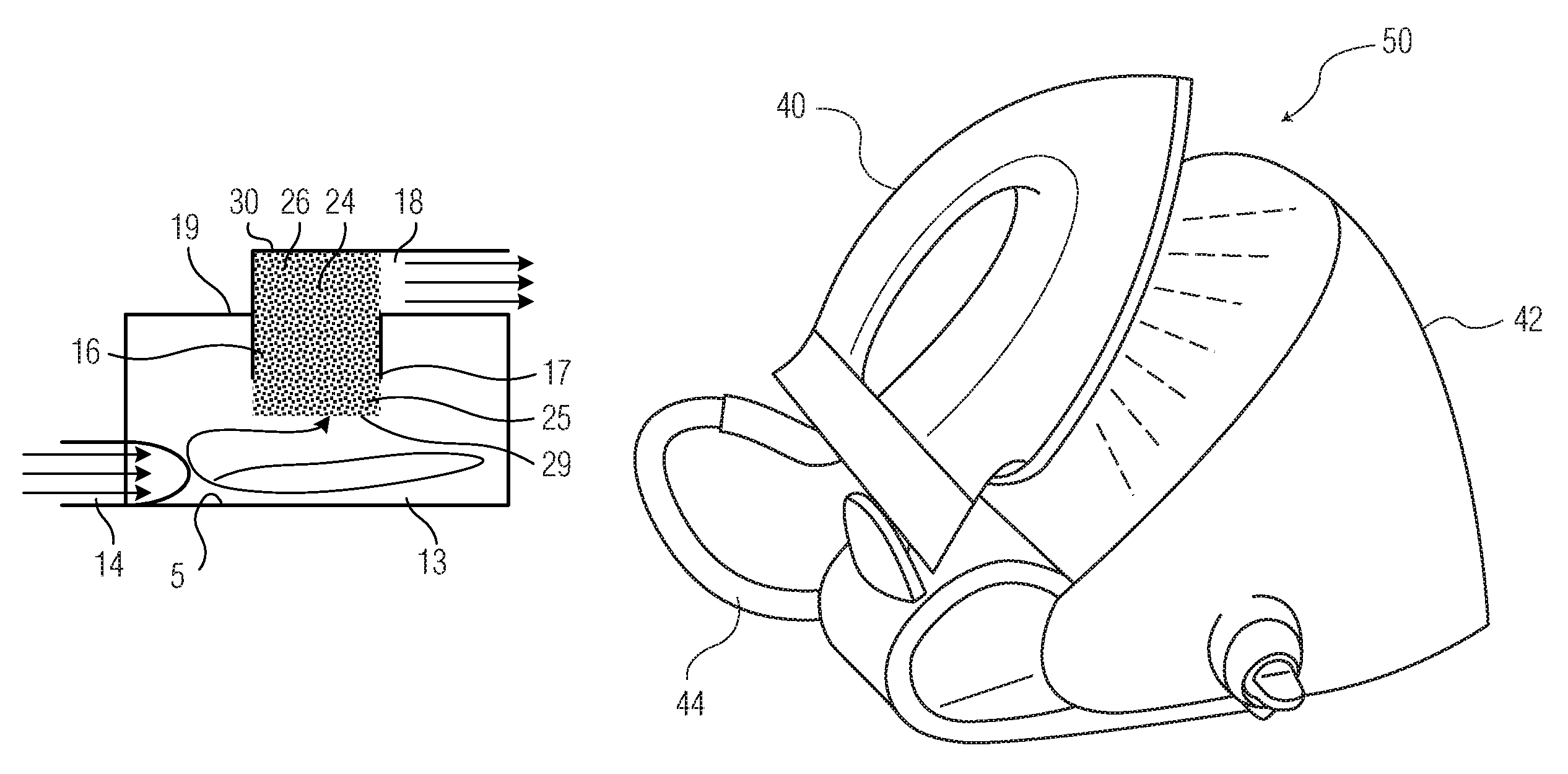
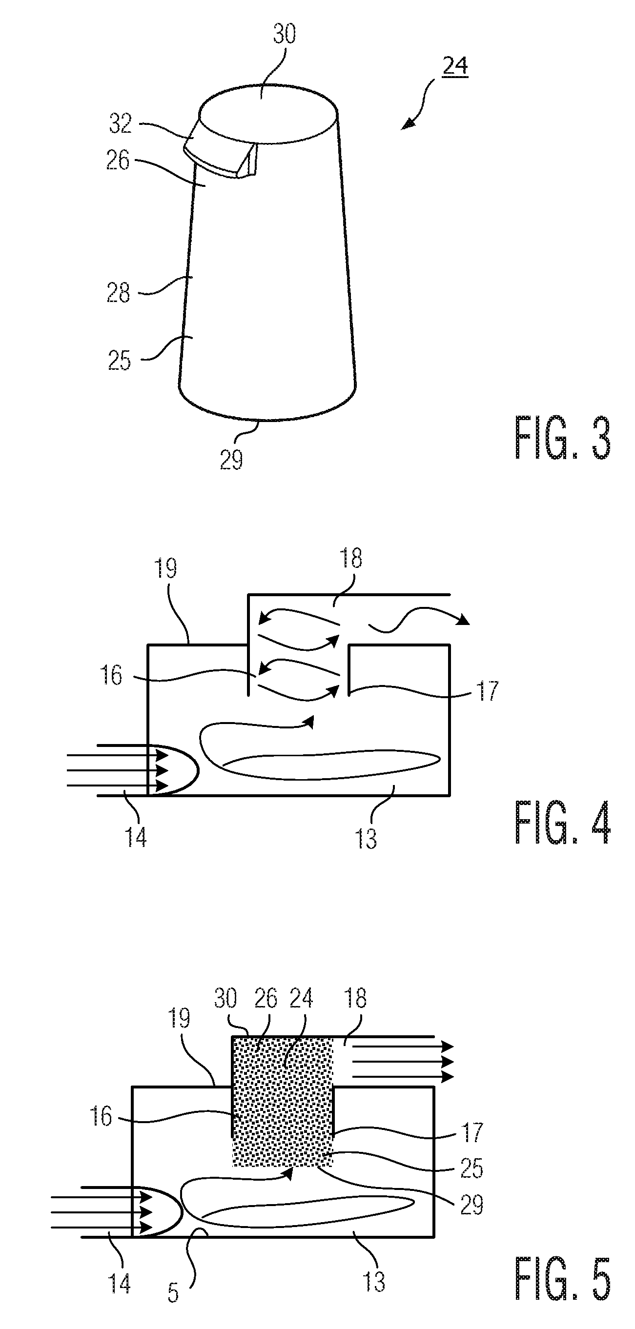
[0007]An advantage of the above arrangement is that the generation of noise at the transition is minimised as steam flows along the steam passageway. This ensures that the noise levels generated during use of the steam generator iron are minimised. The above arrangement also reduces the resistance to flow as the steam flows along the steam passageway by stabilising the flow of steam in the steam passageway. Furthermore, the above arrangement allows for a more compact design.
[0008]The first section may define a cyclonic chamber and the first section may be configured to generate a rotational flow of steam and water in the chamber. Therefore, a cyclonic chamber may be used to minimise the flow of excess water from the steam generator iron whilst minimising the noise level generated by a steam passageway having a cyclonic chamber.
[0010]Conveniently, the flow stabilising element is formed from an intertwined metal wire mesh. This arrangement creates a form-stable and flexible mesh.
[0018]This arrangement allows the noise level at the transition of the steam passageway from a large diameter to a small diameter to be minimised.
[0021]Therefore, the noise level generated by a steam passageway having the above arrangements is minimised.

Problems solved by technology

The above arrangement also reduces the resistance to flow as the steam flows along the steam passageway by stabilising the flow of steam in the steam passageway.

Method used


Image

  • Steam generator iron
  • Steam generator iron
  • Steam generator iron

Examples


Embodiment Construction

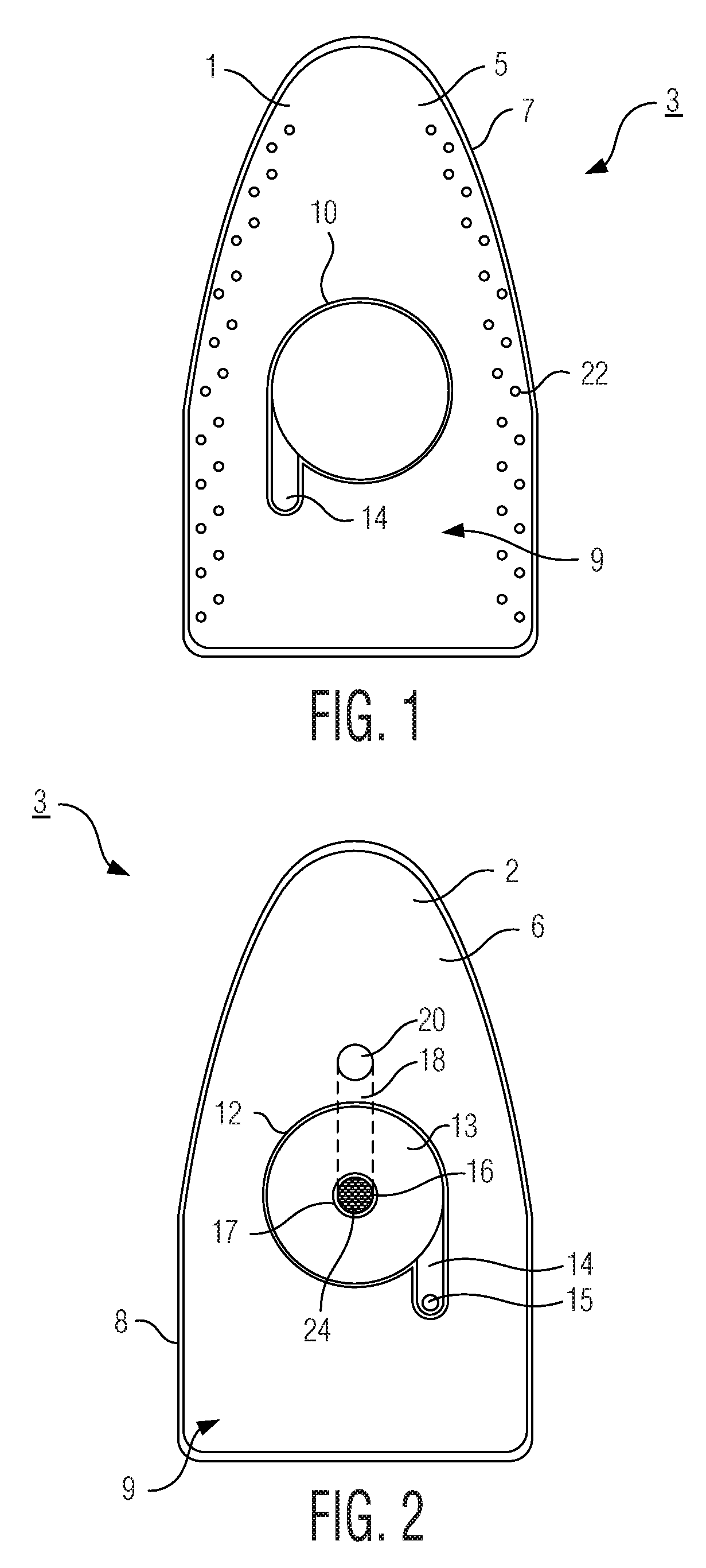
[0039]Referring now to FIGS. 1 and 2, a lower part 1 and an upper part 2 of a sole plate 3 for a steam generator iron is shown. In FIG. 1 a top face 5 of the sole plate lower part 1 is shown, and in FIG. 2 a bottom face 6 of the sole plate upper part 2 is shown. A lower outer rim 7 upstands from and extends around the peripheral edge of the top face 5 of the sole plate lower part 1, and an upper outer rim 8 upstands from and extends around the peripheral edge of the bottom face 6 of the sole plate upper part 2.

[0040]Such a steam generator iron is used to apply steam to a fabric of a garment to remove creases from the fabric. Although the embodiments described below will relate to applying steam to the fabric of a garment, it will be appreciated that such a steam generator iron may be used to remove creases from other fabrics and materials.

[0041]When assembled, the lower and upper parts 1, 2 of the sole plate 3 are fixedly mounted to each other such that the top and bottom faces 5, 6...


PUM


Abstract

The present application relates to a steam generator iron. The steam generator iron has a steam passageway along which steam flows, the steam passageway having a first section (13) and a second section (16) extending from the first section (13). A flow stabilizing element (24, 35, 38) is disposed at the transition of the steam passageway from the first section (13) to the second section (16). Therefore, the generation of noise at the transition and the flow resistance in the steam passageway is minimized as steam flows along the steam passageway. The present application also relates to an insert for a steam generator iron.

Description

[0001]This application is the U.S. National Phase application under 35 U.S.C. §371 of International Application No. PCT / IB2012 / 055901, filed on Oct. 26, 2012, which claims the benefit of U.S. Provisional Application No. 61 / 556,989 filed on Nov. 8, 2011. These applications are hereby incorporated by reference herein.FIELD OF THE INVENTION[0002]The present invention relates to a steam generator iron.BACKGROUND OF THE INVENTION[0003]A steam generator iron is used to remove creases from the fabric of a garment or other material. Such a steam generator iron comprises a head unit having a main body with a handle which is held by a user, and a sole plate with a planar surface which is pressed against the fabric of a garment. A water receiving chamber and a steam generating unit are disposed in the main body, so that water is fed from the water receiving chamber into the steam generating unit and converted into steam. The steam then flows along a steam passageway and is discharged from the ...

Claims


Application Information

Patent Timeline
Patent Type & Authority Patents(United States)
IPC IPC(8): D06F75/12D06F75/20D06F75/10D06F75/38
CPCD06F75/10D06F75/12D06F75/20D06F75/38
Inventor TACK, JOHANNES WILLEM
Owner VERSUNI HLDG BV
Learn More