

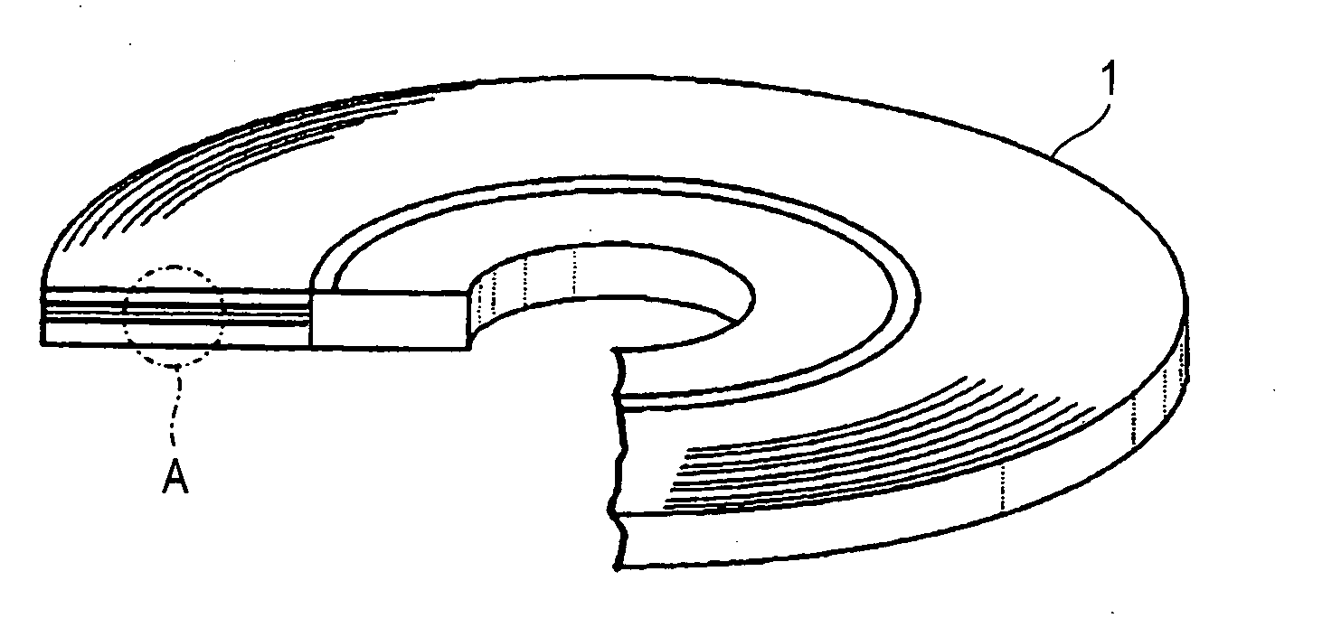
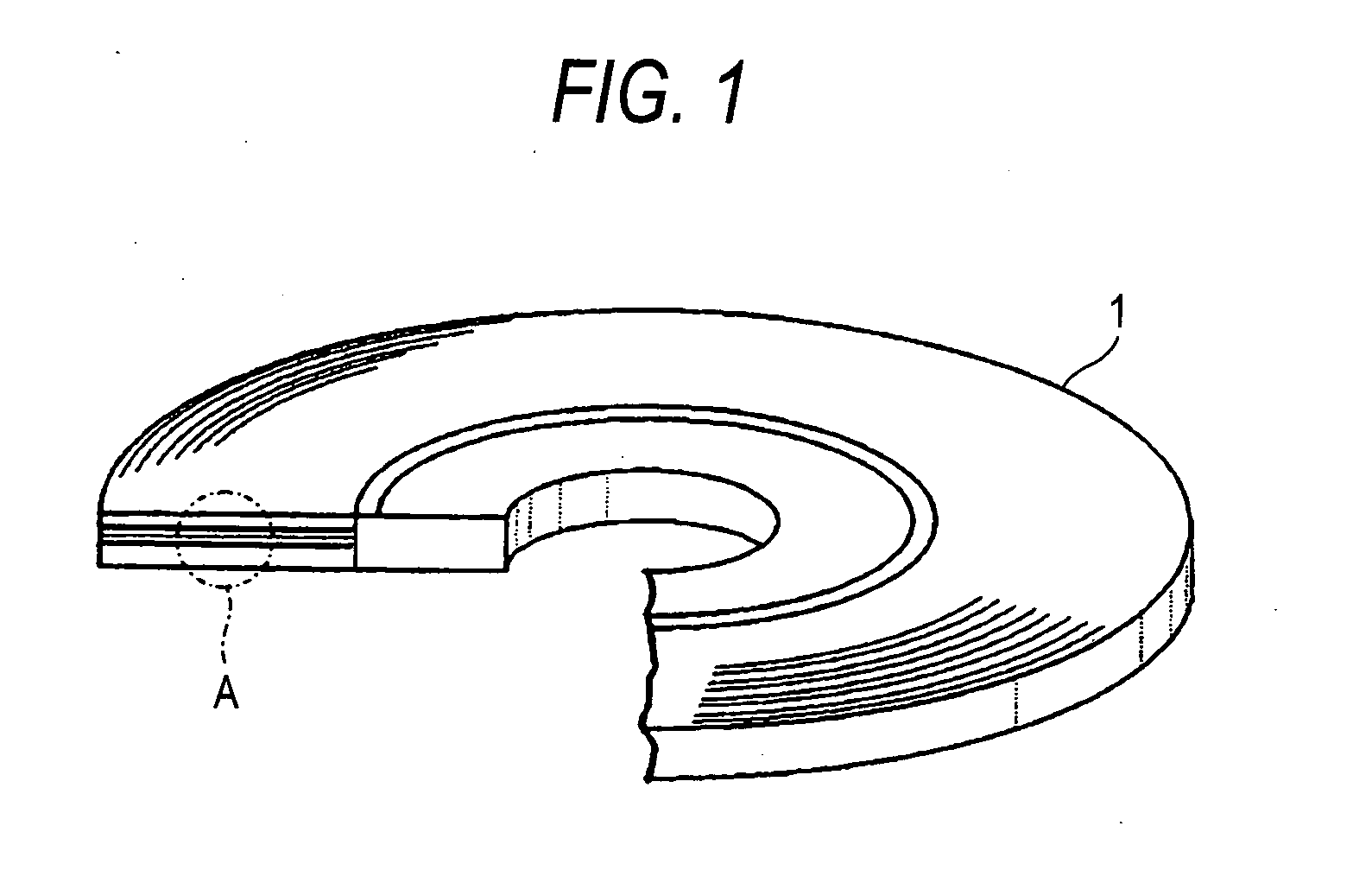
Optical recording medium
a recording medium and optical technology, applied in mechanical recording, recording information storage, instruments, etc., can solve the problems of deterioration of the jitter hard to effectively radiate the heat generated is difficult to form a recording mark and record data on the recording film, etc., to minimize the noise level of the reproducing signal and improve the reproducing effect. , the effect of excellent flatness
- Summary
- Abstract
- Description
- Claims
- Application Information
AI Technical Summary
Benefits of technology
Problems solved by technology
Method used
Image

Examples
example
Example 1
[0121] First of all, a polycarbonate substrate having a thickness of 1.1 mm and a diameter of 120 mm and including a surface provided with a groove and a land at a groove pitch of 0.32 μm was fabricated by injection molding.
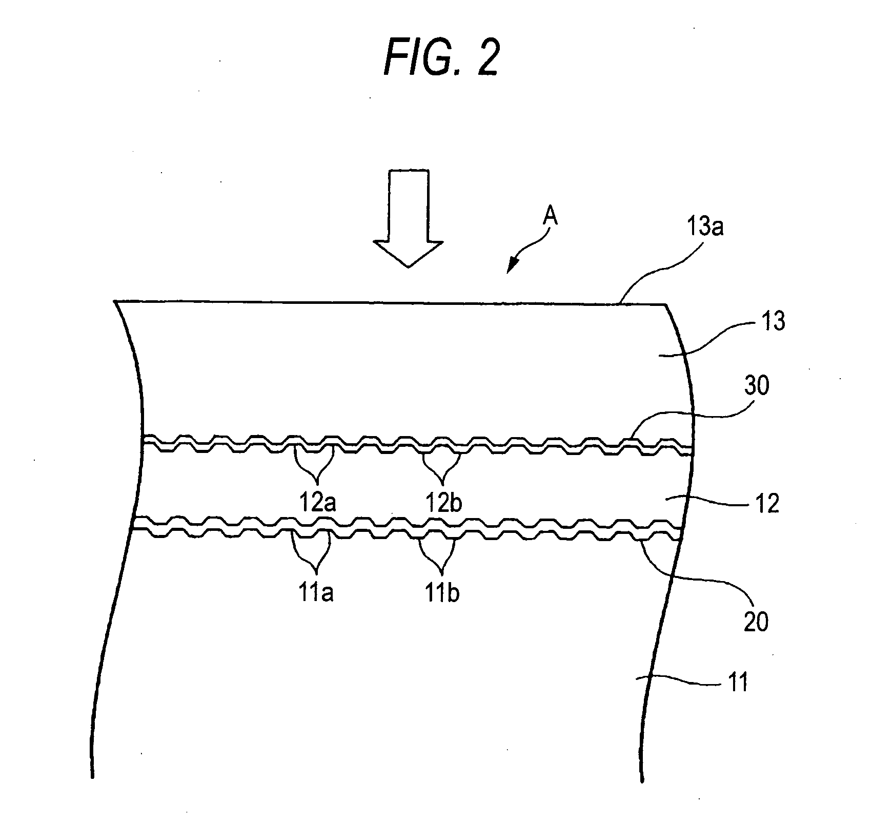
[0122] Next, the polycarbonate substrate was set into a sputtering device, and a reflection film containing an alloy of Ag, Pd and Cu as a main component and having a thickness of 100 nm, a second dielectric film containing a mixture of ZnS and SiO2 at a mole ratio of 50:50 as a main component and having a thickness of 10 nm, a recording film containing, as a main component, a phase transition material having an atomic composition of Sb77.1Te18.7Ge4.2 and having a thickness of 12 nm, a first dielectric film containing a mixture of ZnS and SiO2 at a mole ratio of 80:20 as a main component and having a thickness of 20 nm, and a radiation film containing aluminum nitride as a main component and having a thickness of 30 nm were sequentially formed, by sput...
example 2
[0140] A polycarbonate substrate was set into a sputtering device and a dielectric film containing zirconium oxide as a main component and having a thickness of 50 nm was formed on the surface of the polycarbonate substrate on the same film forming conditions as those in the formation of the fourth dielectric film in the second information layer of the sample #1, and a sample #1-1 was thus formed.
[0141] By using an X-ray diffracting apparatus “ATX-G” (trade name) manufactured by Rigaku Corporation, furthermore, the structure of the dielectric film was analyzed for the sample #1-1. As a result, it was found that the dielectric film was set in a crystalline state having a cubic crystalline structure, and furthermore, the crystal grain size of each crystal was equal to or smaller than 20 nm.
[0142] Subsequently, a comparative sample #1-1 was fabricated in the same manner as the sample #1-1 on the same film forming conditions as those in the formation of the fourth dielectric film in t...
PUM
| Property | Measurement | Unit |
|---|---|---|
| thickness | aaaaa | aaaaa |
| thickness | aaaaa | aaaaa |
| crystal grain size | aaaaa | aaaaa |
Abstract
Description
Claims
Application Information