Patient chair lift

a technology for patients and chairs, applied in the field of patient chairs, to achieve the effect of convenient and efficient manufacture and marketing, low manufacturing cost, and durable and reliable construction

Inactive Publication Date: 2009-11-03
ROBERTS CAMERON B +1
View PDF13 Cites 27 Cited by
  • Summary
  • Abstract
  • Description
  • Claims
  • Application Information

AI Technical Summary

Benefits of technology

[0019]It is therefore an object of the present invention to provide a new and improved patient chair lift which has all of the advantages of the prior art patient lifting systems of known designs and configurations and none of the disadvantages.
[0020]It is another object of the present invention to provide a new and improved patient chair lift which may be easily and efficiently manufactured and marketed.
[0021]It is further object of the present invention to provide a new and improved patient chair lift which is of durable and reliable constructions.
[0022]An even further object of the present invention is to provide a new and improved patient chair lift which is susceptible of a low cost of manufacture with regard to both materials and labor, and which accordingly is then susceptible of low prices of sale to the consuming public, thereby making such patient chair lift economically available to the buying public.
[0023]Even still another object of the present invention is to provide a patient chair lift for facilitating the lifting and transporting of a patient in a safe, convenient and economical manner.

Problems solved by technology

While these devices fulfill their respective, particular objectives and requirements, the aforementioned patents do not describe a patient chair lift that allows for facilitating the lifting and transporting of a patient in a safe, convenient and economical manner.

Method used


Image

  • Patient chair lift
  • Patient chair lift
  • Patient chair lift

Examples


Embodiment Construction

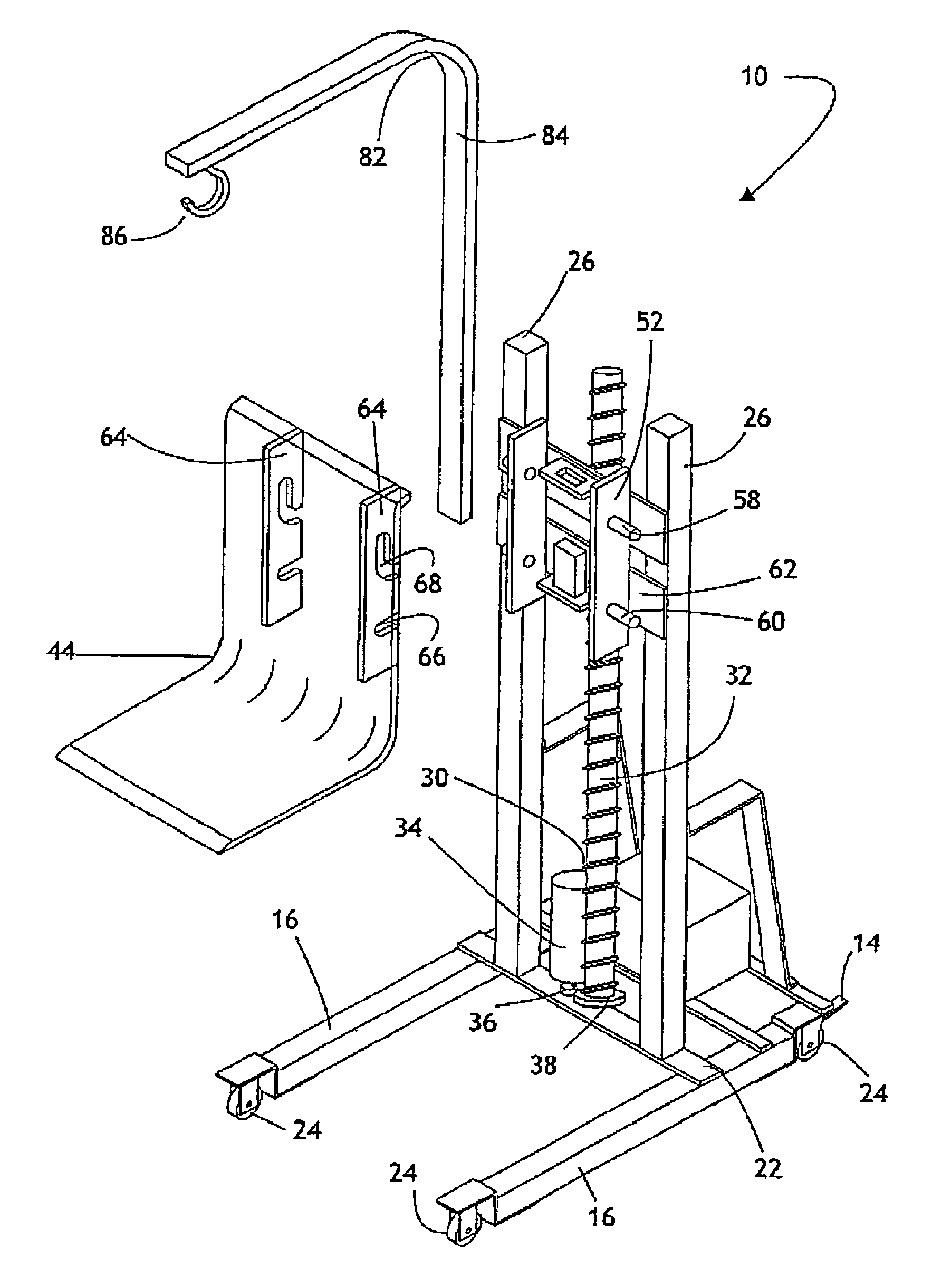
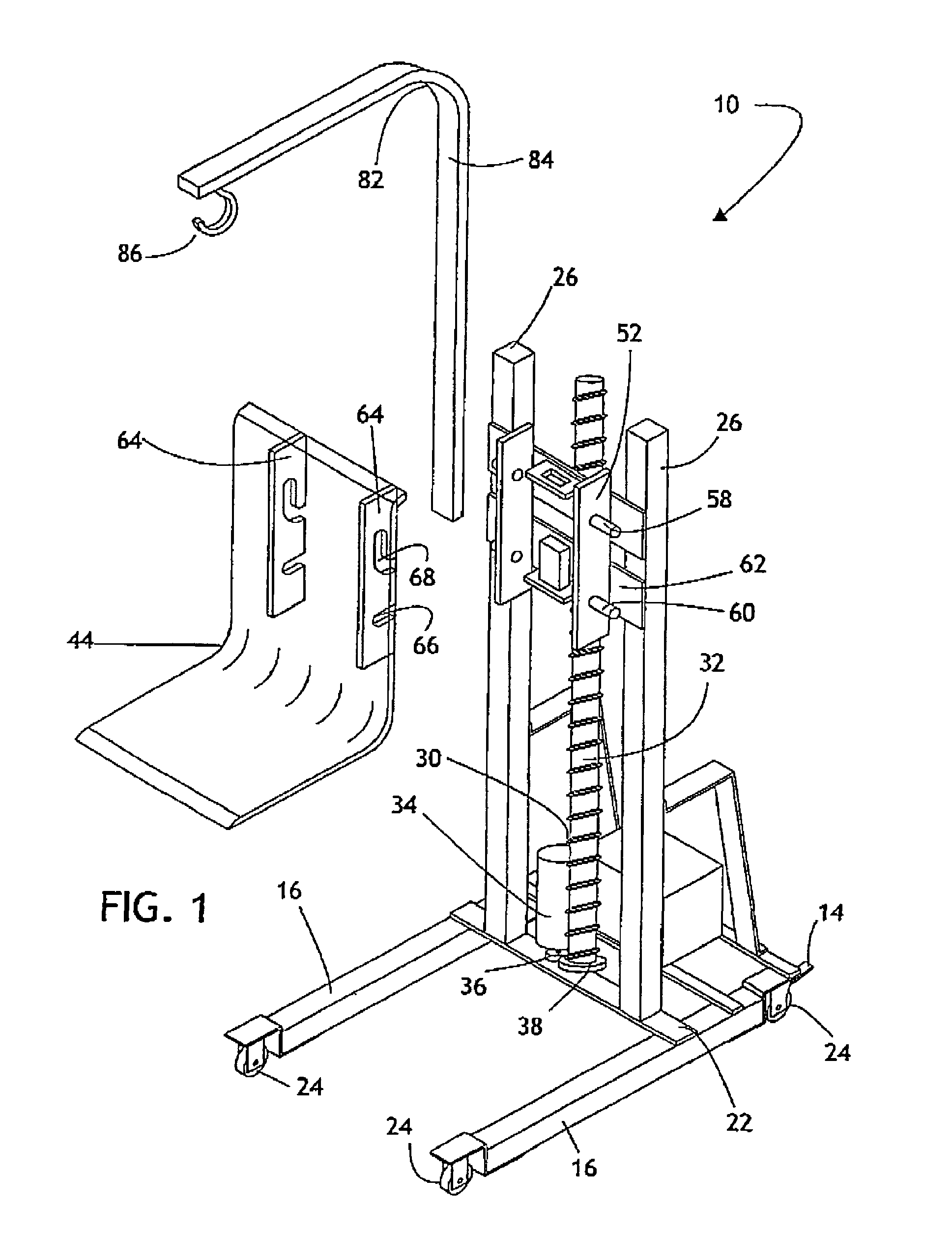
[0030]With reference now to the drawings, and in particular to FIG. 1 thereof, the preferred embodiment of the new and improved patient chair lift embodying the principles and concepts of the present invention and generally designated by the reference numeral 10 will be described.

[0031]The present invention, the patient chair lift 10 is comprised of a plurality of components. Such components in their broadest context include a frame assembly, a drive screw, a chair, a separable securement area and a control assembly. Such components are individually configured and correlated with respect to each other so as to attain the desired objective.

[0032]First provided is a frame assembly 14. The frame assembly is formed of laterally spaced horizontal side rails 16. The side rails have front ends 18. The side rails have rear ends 20. A horizontal cross rail 22 is provided. The cross rail spans the side rails. The frame assembly includes wheels 24. The wheels are secured beneath the front ends...


PUM


Abstract

A frame assembly is formed of side rails with a cross rail and spaced vertical support rails. A drive screw is positioned on the cross rail. A motor and a follower are received on the jack screw. The follower may move upwardly and downwardly on the drive screw. A chair has a seat portion and a back portion and is movable between a raised orientation and a lowered orientation on the floor. A separable securement area couples the seat portion with the follower. A control assembly includes an up button and a down button and a stop button.

Description

BACKGROUND OF THE INVENTION[0001]1. Field of the Invention[0002]The present invention relates to a patient chair lift and more particularly pertains to facilitating the lifting and transporting of a patient in a safe, convenient and economical manner.[0003]2. Description of the Prior Art[0004]The use of Patient chair lifts is known in the prior art. More specifically, patient lifting systems of known designs and configurations previously devised and utilized for the purpose of lifting a patient through known methods and apparatuses are known to consist basically of familiar, expected, and obvious structural configurations, notwithstanding the myriad of designs encompassed by the crowded prior art which has been developed for the fulfillment of countless objectives and requirements.[0005]By way of example, U.S. Pat. No. 5,456,655 issued Oct. 10, 1995 to Morris relates to an Ambulatory Support System for Patients. U.S. Pat. No. 5,708,993 issued Jan. 20, 1998 to Campbell relates to a P...

Claims


Application Information

Patent Timeline
Patent Type & Authority Patents(United States)
IPC IPC(8): A47C1/00A61G7/10
CPCA61G7/1011A61G7/1019A61G7/109A61G7/1059A61G7/1046
Inventor ROBERTS, CAMERON B.CHANG, JERRY K.
Owner ROBERTS CAMERON B
Why Eureka
Try Eureka