Adaptive optics for compensating for optical aberrations in an imaging process

a technology of adaptive optics and imaging process, applied in optics, othalmoscopes, medical science, etc., can solve the problems of so-called lower order aberration, additional asymmetrical aberration, and significant damage, and achieve the effect of reducing the compensation burden

Active Publication Date: 2009-11-03
HEIDELBERG ENGINEERING GMBH
View PDF12 Cites 27 Cited by
  • Summary
  • Abstract
  • Description
  • Claims
  • Application Information

AI Technical Summary

Benefits of technology

[0016]An intended application for the device of the present invention is as an aberration compensator in an imaging system that is to be used for ophthalmic laser surgery. Typically, such systems incorporate a MEMS mirror to compensate for the higher order aberrations and the symmetrical aberrations associated with myopia, hyperopia and spherical aberration. When used in such a system, in combination with a MEMS mirror, the present invention is able to reduce the compensation burden that would otherwise be required by the MEMS mirror acting alone. In particular, this will be so when compensation for asymmetrical aberrations is desired.

Problems solved by technology

Insofar as imaging is concerned, it happens that the so-called lower order aberrations (i.e. 2nd, 3rd and 4th order) can be significantly detrimental.
Along with the 2nd order aberrations just mentioned, however, additional asymmetrical aberrations in the 3rd and 4th orders can also be significantly detrimental to human vision.
This is particularly so under relatively poor lighting conditions.

Method used


Image

  • Adaptive optics for compensating for optical aberrations in an imaging process
  • Adaptive optics for compensating for optical aberrations in an imaging process
  • Adaptive optics for compensating for optical aberrations in an imaging process

Examples


Embodiment Construction

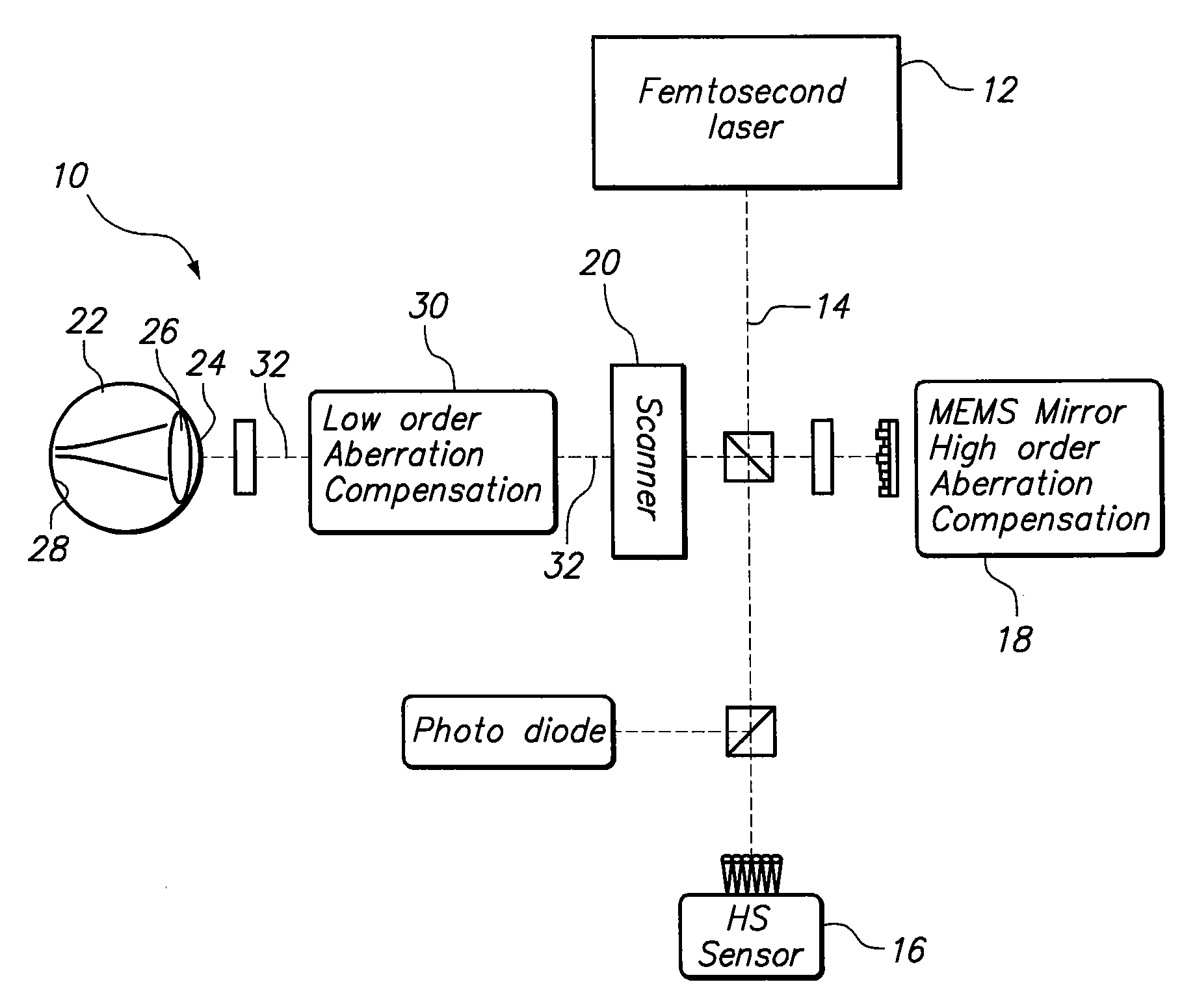
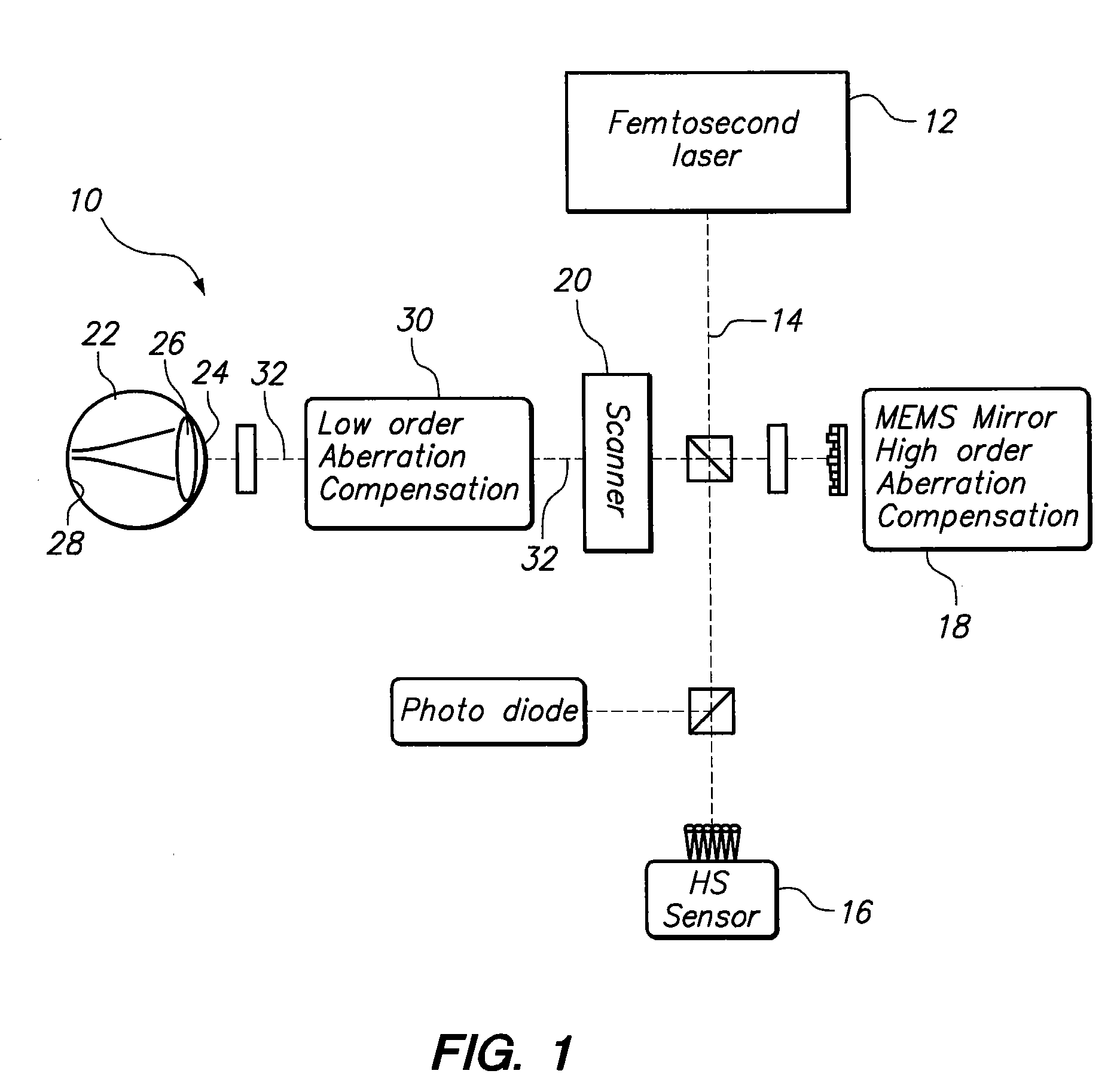
[0021]Referring initially to FIG. 1, an optical system for incorporating the present invention is shown and generally designated 10. As shown, the system 10 includes a laser source 12 for generating a laser beam 14. Through electronic connections, not shown in FIG. 1, this laser beam 14 is then monitored by a sensor 16 (preferably a Hartmann Shack type sensor), it is also refined by a MEMS mirror 18 that removes certain aberrations from the laser beam 14, and it is controlled by a scanner 20. More specifically, the scanner 20 can be preprogrammed to direct the laser beam 14 toward an eye 22 for various purposes. Specifically, the eye 22 has a cornea 24, a lens 26 and a retina 28 that can be imaged or be operated on by a surgical laser beam 14. FIG. 1 also shows that a compensation device 30 is positioned between the scanner 20 and the eye 22, and that the laser beam 14 will pass through the compensation device 30 along a beam path axis 32.

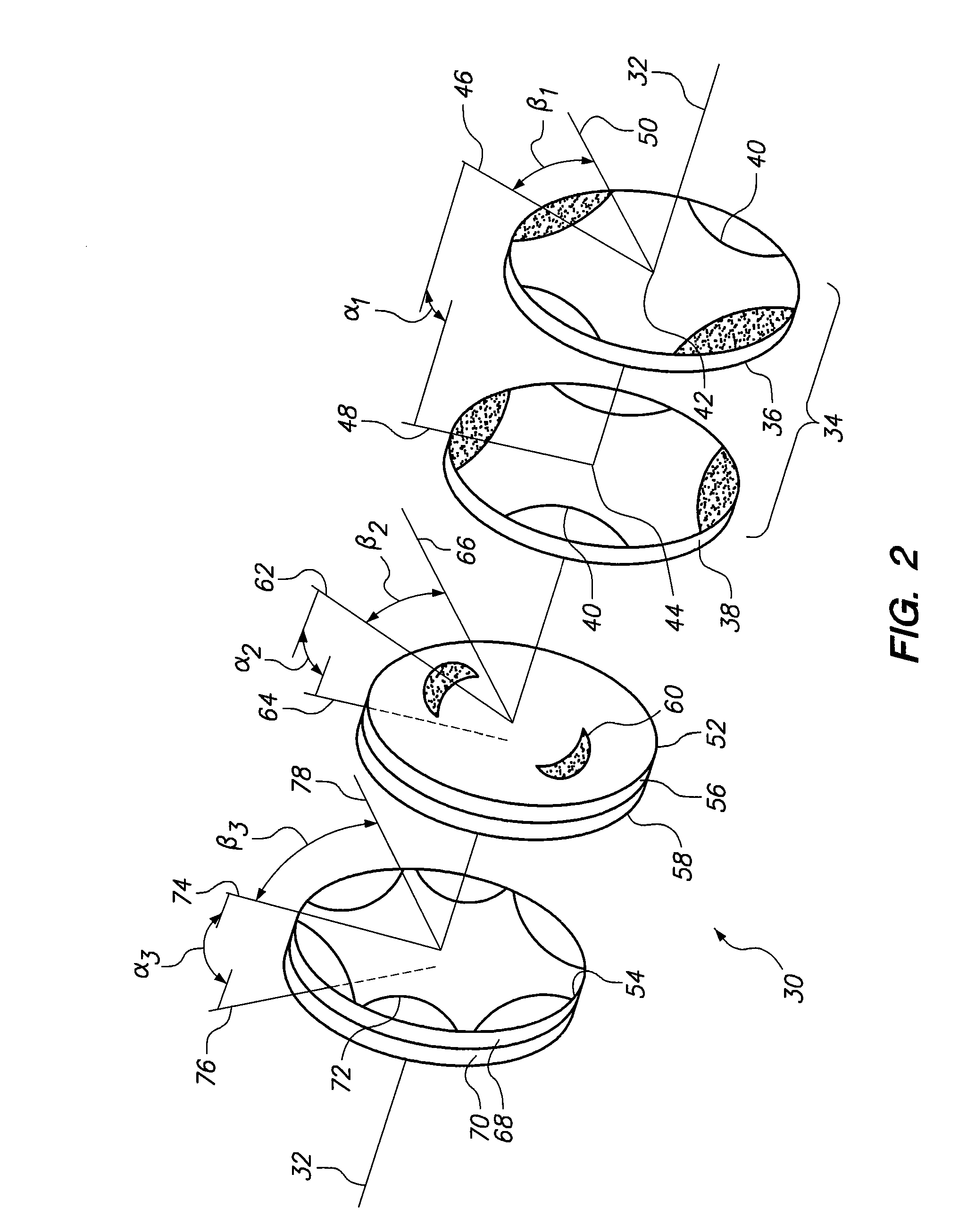
[0022]Referring now to FIG. 2 it will be see...


PUM


Abstract

A device to compensate for asymmetrical aberrations in a beam of light includes at least one dual compensator positioned on the beam path. Structurally, the dual compensator includes two juxtaposed plates, each having a same pattern presented thereon. The patterns, however, are rotated through an angle α relative to each other. Together, the plates of the dual compensator can then be rotated on the beam path through an angle β to compensate for asymmetrical aberrations in the light beam. Dual compensators, having appropriate patterns, can be collectively used to compensate for astigmatism, coma and trefoil.

Description

[0001]This application is a continuation-in-part of application Ser. No. 10 / 718,406, filed Nov. 20, 2003, now U.S. Pat. No. 7,510,283 which is currently pending. The contents of application Ser. No. 10 / 718,406 are incorporated herein by reference.FIELD OF THE INVENTION[0002]The present invention pertains generally to systems for correcting optical imaging. More particularly, the present invention pertains to systems that compensate for optical aberrations when they are introduced into a light beam by a human eye. The present invention is particularly, but not exclusively, useful as a system and device that compensates for the lower order asymmetrical aberrations in an eye, such as astigmatism, coma and trefoil.BACKGROUND OF THE INVENTION[0003]In vision science it is common to represent errors of the eye as wavefront aberrations. When doing this, there are various kinds of mathematical representations that can be used. In particular, polynomials, such as the Zernike polynomials, are ...

Claims


Application Information

Patent Timeline
Patent Type & Authority Patents(United States)
IPC IPC(8): A61B3/10A61B3/00A61B3/12
CPCA61F9/0084G02B26/06G02B27/0068A61F2009/00872
Inventor BILLE, JOSEF
Owner HEIDELBERG ENGINEERING GMBH
Why Eureka
Try Eureka