
Efficient light injector

a technology of efficient light and light source, applied in the direction of fibre light guide, lighting and heating apparatus, instruments, etc., can solve the problems of difficult coupling of light from a lambertian led source, and the efficiency of packaging leds is not often optimized, so as to maximize efficiency and maximize efficiency. the effect of collection and transmission of ligh

Inactive Publication Date: 2009-11-03
3M INNOVATIVE PROPERTIES CO
View PDF23 Cites 25 Cited by
  • Summary
  • Abstract
  • Description
  • Claims
  • Application Information

AI Technical Summary

Benefits of technology

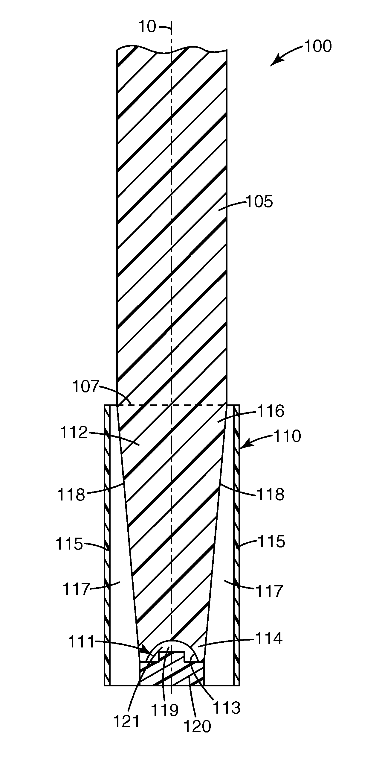
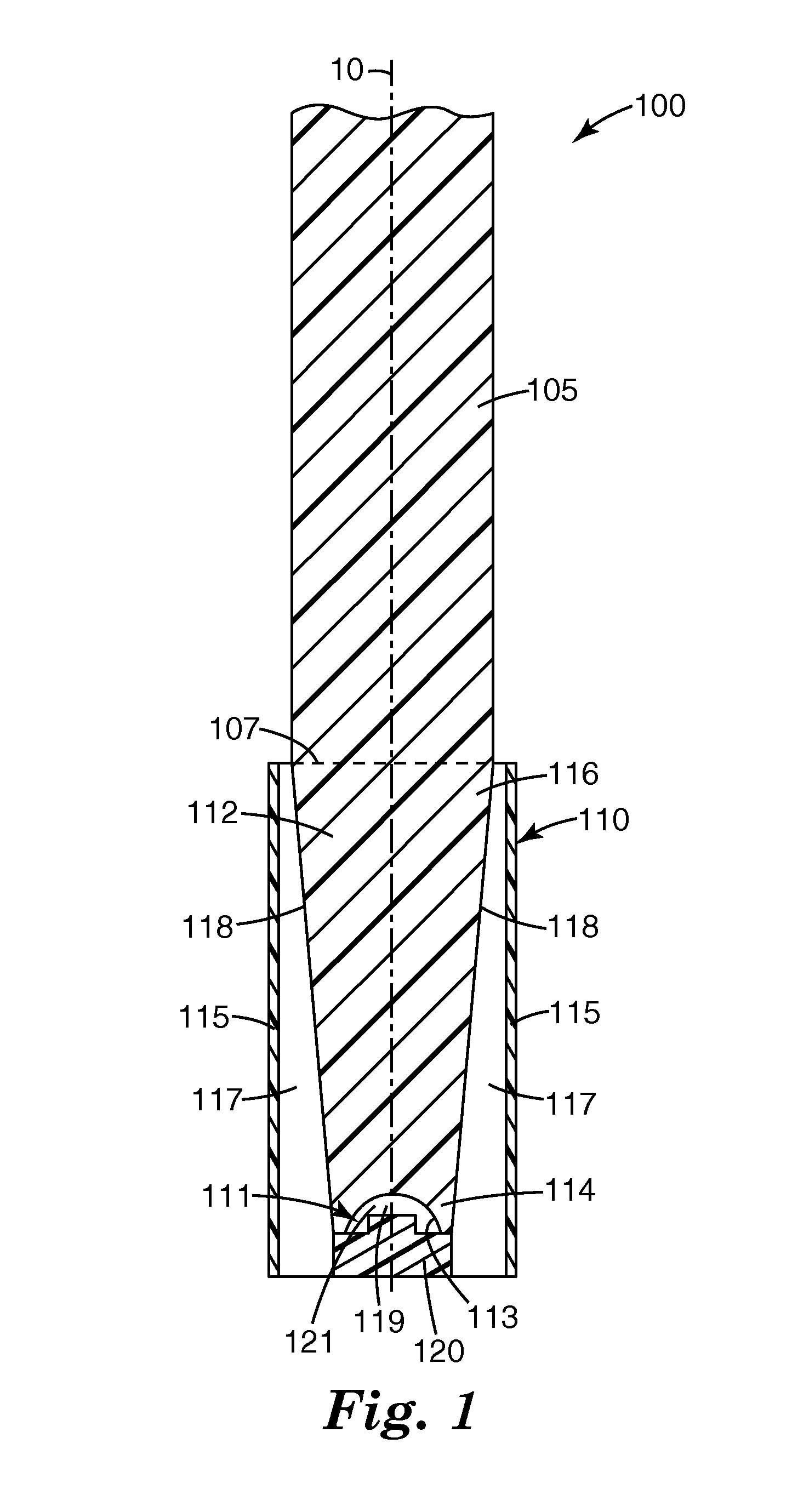
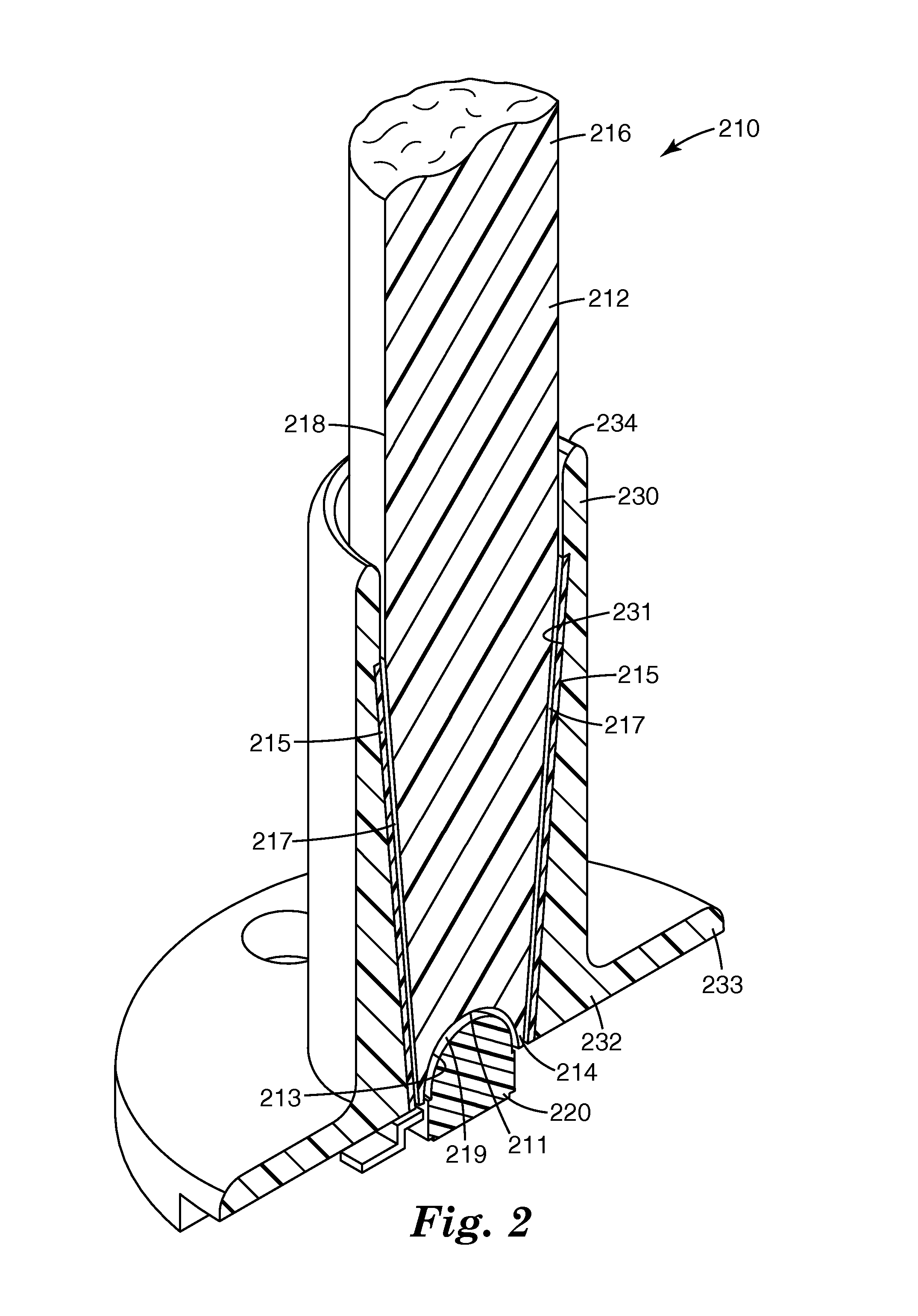
The present patent is about a new light collector and injector that can efficiently collect and transmit light from lambertian light sources. The light collector uses both specular reflectivity and total internal reflection to maximize efficiency. The light injector has a tapered solid light guide with a light input end, an opposing light output end, and a total internal reflection surface. A specularly reflective layer or film is adjacent to the total internal reflection surface, and a distance between the reflective layer and the total internal reflection surface defines an air gap. The light injector can be used in illumination assemblies that include an elongated cylindrical light guide. The technical effects of this patent are improved efficiency in collecting and transmitting light from lambertian light sources.

Problems solved by technology

However, packaged LEDs are not often optimized for any particular application and designers go to lengths to collect and direct light output for a particular use.
Light that is not efficiently utilized is effectively wasted.
Collecting light from a lambertian LED source and coupling that light into a light guide is often difficult since this light emitted in all directions from the LED and this light must be redirected into the numerical aperture of the light guide where it can be efficiently maintained by total internal reflection.
When a simple reflector is used, the imperfect specular reflectivity of the reflection surface means that some portion of the light is lost on every reflection bounce.
This aspect ratio also means a relatively large number of bounces for light traversing the reflector, and more bounces equate to more loss.

Method used


Image

  • Efficient light injector
  • Efficient light injector
  • Efficient light injector

Examples


Embodiment Construction

[0014]In the following description, reference is made to the accompanying drawings that form a part hereof, and in which are shown by way of illustration several specific embodiments. It is to be understood that other embodiments are contemplated and may be made without departing from the scope or spirit of the present invention. The following detailed description, therefore, is not to be taken in a limiting sense.

[0015]All scientific and technical terms used herein have meanings commonly used in the art unless otherwise specified. The definitions provided herein are to facilitate understanding of certain terms used frequently herein and are not meant to limit the scope of the present disclosure.

[0016]Unless otherwise indicated, all numbers expressing feature sizes, amounts, and physical properties used in the specification and claims are to be understood as being modified in all instances by the term “about.” Accordingly, unless indicated to the contrary, the numerical parameters s...


PUM


Abstract

A light injector includes a tapered solid light guide having a light input end, an opposing light output end, and a total internal reflection surface defining a longitudinal outer surface there between. The light input end includes an aperture extending into the tapered solid light guide defined by an aperture surface. A specularly reflective layer or film is disposed adjacent to the total internal reflection surface. A distance between the specularly reflective layer or film and the total internal reflection surface defines a first air gap. The aperture is configured to accept a lambertian light source.

Description

FIELD[0001]The present disclosure relates to efficient light injectors and particularly to tapered solid light injectors that efficiently transmit light from a lambertian light source.BACKGROUND[0002]Solid state light sources such as light emitting diodes (LEDs) are often preferred light sources for many applications because of their small size, pure colors, and long lifetime. However, packaged LEDs are not often optimized for any particular application and designers go to lengths to collect and direct light output for a particular use. Light that is not efficiently utilized is effectively wasted.[0003]Optically transmissive materials, such as glass or polymers may be used as a light guide to propagate light. A light guide often includes at least one surface adapted to receive light from a light source and an optically smooth surface for reflecting light propagating through the light guide. Common examples of light guides include optical fibers traditionally used in the data communi...

Claims


Application Information

Patent Timeline
Patent Type & Authority Patents(United States)
IPC IPC(8): F21V33/00
CPCG02B6/0006G02B6/4203G02B6/262G02B6/4212G02B6/26G02B6/42
Inventor MEIS, MICHAEL A.LUNDIN, DAVID J.GULLICKS, SCOTT D.HOYLE, CHARLES D.
Owner 3M INNOVATIVE PROPERTIES CO
Learn More