Structure and method for stopping water in shielded electric wire

a technology of shielded electric wires and structures, applied in the direction of insulated conductors, cable terminations, cables, etc., can solve the problems of not being able to achieve sufficient water stopping ability, air drawing equipment is required, and the adhesive is not applied into the shield member, so as to ensure the bonding effect, the effect of reliably blocking the water stopping part from the outsid

Active Publication Date: 2009-11-03
YAZAKI CORP
View PDF10 Cites 16 Cited by
  • Summary
  • Abstract
  • Description
  • Claims
  • Application Information

AI Technical Summary

Benefits of technology

[0008]The invention has been made to solve the above problems and an advantage to provide a structure and method for stopping water in a shielded electric wire in a simple and reliable with low cost.
[0012]According to the first aspect of the invention, by the heat shrinkage of the heat shrinkable tube, while applying a pressure, since it is possible to permeate the adhesive into the shield member and harden the adhesive, the sufficient application of adhesive onto the required portions is possible. Moreover, since the adhesive is hardened in a pressurized state, bonding is surely performed. In particular, since it is possible to bury the gaps of heat shrinkable tube with the shielded electric wire by the hot melt, not only it is possible to permeate an adhesive uniformly into the shield member, but also it is possible to reliably block the water stopping part from the outside. As a result, water stopping ability can be reliably ensured for a long time, and the infiltrations of moistures through the shield member can be blocked.
[0013]In addition, since the water stopping part is protected by the heat shrinkable tube, it is possible to increase durability. Moreover, since resistance to the thermal expansion due to the temperature change or the external force is exhibited, it is possible to avoid the shape collapse thereof by keeping the shape of the hardening adhesive, and the handling of the shielded electric wire is easily performed while maintaining high water stop ability.
[0015]According to the second aspect of the invention, since the water stopping structures in the first aspect of the invention can be easily obtained without using air drawing-out equipment of high cost, it is also possible to obtain the effect of the first aspect of the invention. In addition, it is possible to shorten the hardening time of the adhesive in accordance with a kind of adhesive when the temperature of the heat shrinkable tube increases.
[0016]According to the third aspect of the invention, since the infiltrations of the adhesive onto the shield member is performed by permeating the stripped part into the adhesive contained in a container, it is possible to apply sufficient amount of adhesives onto the shield member for a short time with simple equipment.

Problems solved by technology

However, in case of stopping water in the shielded electric wire in which a shielding member (braid, metal foil, and networked brace metal, etc.) surrounding the core at an inner side of an outer shell (sheath) is arranged, the water stopping of the shield member should be considered as well as the water stopping of the core, but since an adhesive is simply applied onto the exposed part of the shield member in the past, it is not possible to obtain effective permeation of the adhesive into the shield member, and sufficient water stopping ability may not be attained.
Meanwhile, a technique which draws out air from a terminal other than the supplying side of the adhesive is proposed, but there exist problems in that air drawing equipment is required, and the operation is difficult, so it does not meet cost conditions.

Method used


Image

  • Structure and method for stopping water in shielded electric wire
  • Structure and method for stopping water in shielded electric wire
  • Structure and method for stopping water in shielded electric wire

Examples


Embodiment Construction

[0021]Hereinafter, embodiments of the invention will be described with reference to the accompanying drawings.

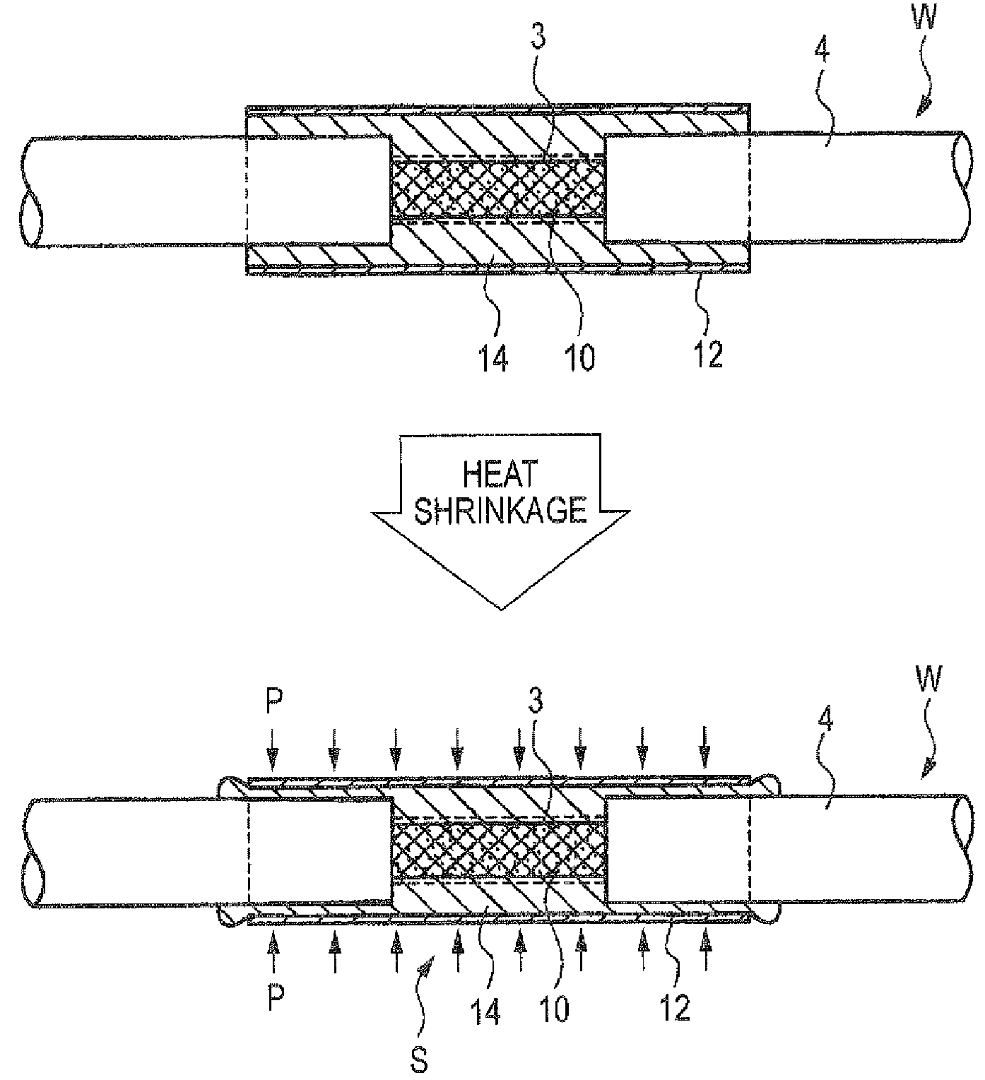
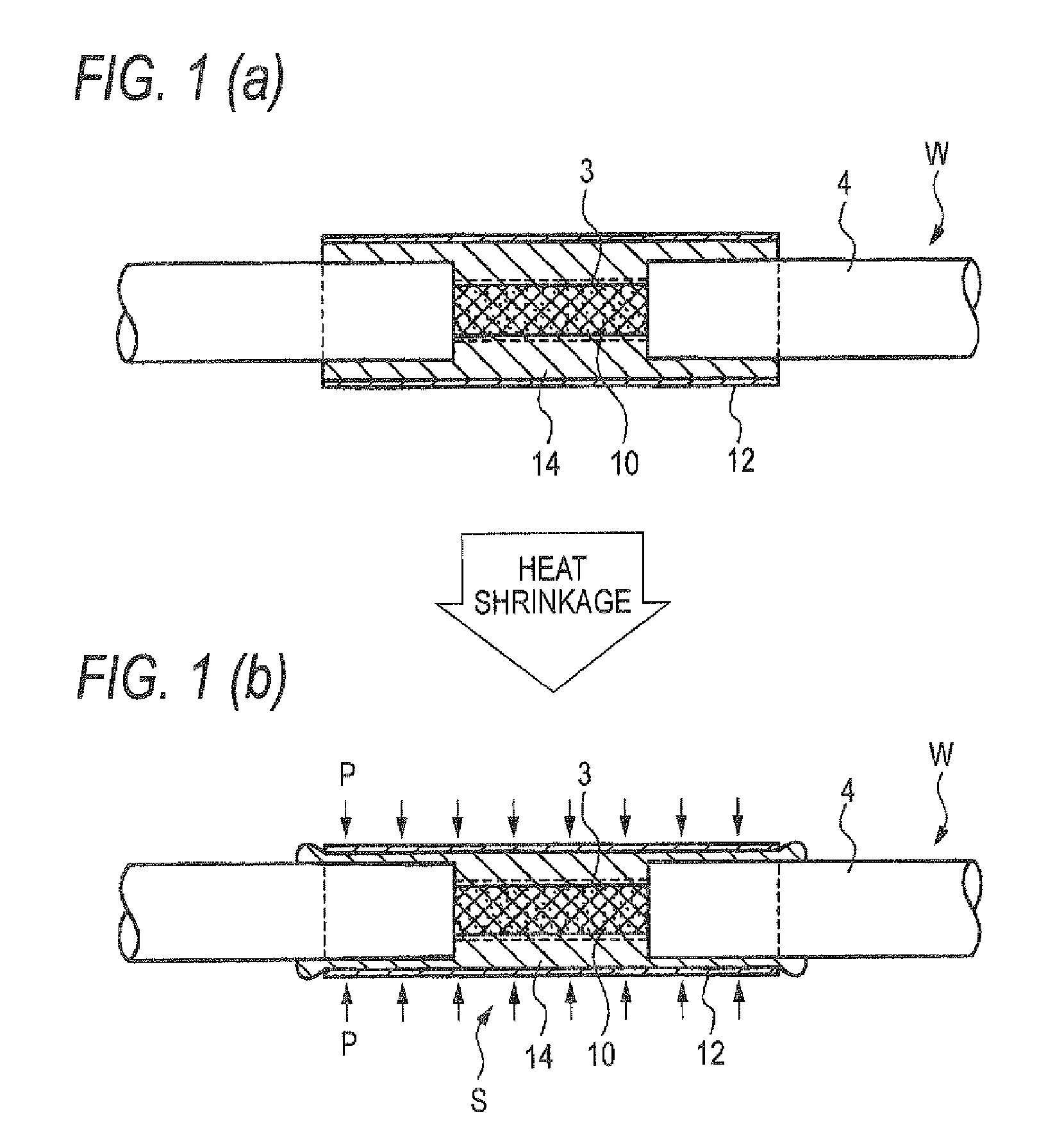
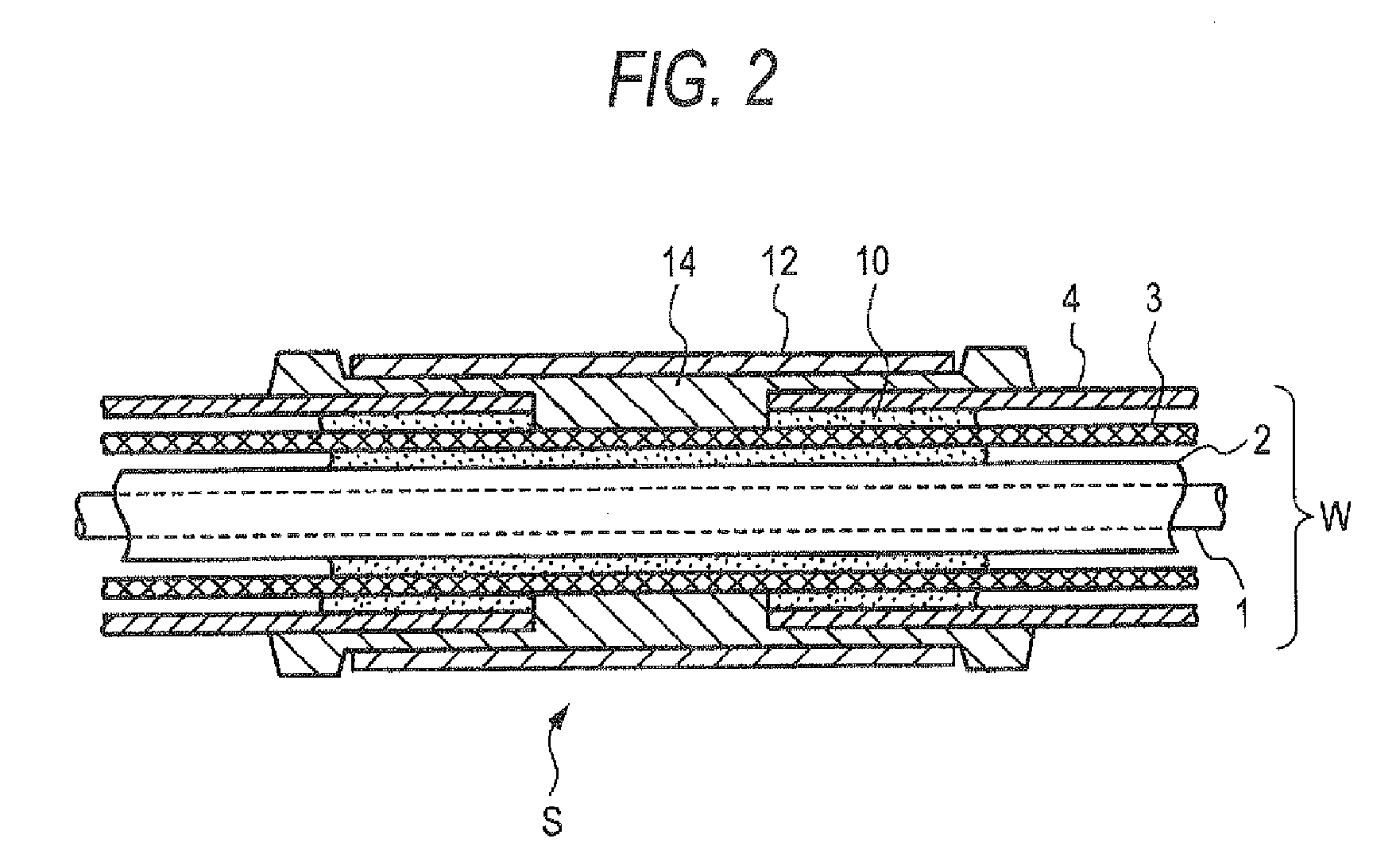
[0022]FIG. 1 is a schematic view of an embodiment of the water stop structure of the shielded electric wire, in which, FIG. 1a shows a cross sectional view on a state before shrinking a heat shrinkable tube, and FIG. 1b shows a cross sectional view on a state after the shrinking of the heat shrinkable tube, FIG. 2 is a detailed sectional view of the FIG. 1a, FIG. 3 is a perspective view of the stripped portion of the shielded electric wire, and FIGS. 4a and 4b are explanatory views of an embodiment of the water stop structure of the shielded electric wire.

[0023]To obtain the water stopping structures of the embodiment, at first, as shown in the FIG. 3, from the structures of shielded electric wire, which comprising a core 1, an insulating layer 2, a shield member 3 (braid, metal foil, and networked brace metal, etc.), and a sheath 4 are arranged in this order, and the middle...


PUM


Abstract

To simply provide a water-stopping structures for shielded electric wire in the shielded portion of the wire at a low cost, a water stop structure in a shielded electric wire is comprised by stripping a sheath 4 of the shielded electric wire in the middle part thereof; permeating an adhesive into the exposed shield member 3; overlaying a heat shrinkable tube 12 over the shield member via hot melt 14; and heat shrinking the heat shrinkable tube 12 in a state where both ends of the heat shrinkable tube 12 are overlapped with the outer periphery of the sheath 4.

Description

BACKGROUND OF THE INVENTION[0001]1. Field of the Invention[0002]The present invention relates to a structure and method for stopping water in a shielded electric wire.[0003]2. Description of the Related Art[0004]It is known that a structure for stopping water infiltrations through the gaps inside the covering material in a electric wire by permeating an adhesive having a flow ability into the inside of the covering material which covers core of wire and hardening the adhesive.[0005]In this case, for example, as described in JP-A-2004-355851, the adhesive is surely permeated into a wide area by supplying the adhesive from one end of the electric wire and drawing out air from the covering material from the other end of the electric wire.[0006]However, in case of stopping water in the shielded electric wire in which a shielding member (braid, metal foil, and networked brace metal, etc.) surrounding the core at an inner side of an outer shell (sheath) is arranged, the water stopping of ...

Claims


Application Information

Patent Timeline
Patent Type & Authority Patents(United States)
IPC IPC(8): H02G15/02
CPCH01B7/285H01R4/72Y02A30/14
Inventor ICHIKAWA, HIDEHIROYAMAMOTO, KOUICHIHASHIZAWA, SHIGEMI
Owner YAZAKI CORP
Why Eureka
Try Eureka