Electrical phase checking apparatus and method of metering

a technology of electric phase checking and metering method, which is applied in the direction of voltage-current phase angle, dynamo-electric motor meters, instruments, etc., can solve the problems of inability to ensure that the proper “phasing” of the cts (with respect to the corresponding voltage measurement) is being maintained, insidious mis-wired meter, and high labor costs and data loss, so as to ensure the accuracy of cts and corresponding voltage measurement, easy to quick indication

Active Publication Date: 2009-11-03
DENT INSTR INC
View PDF3 Cites 8 Cited by
  • Summary
  • Abstract
  • Description
  • Claims
  • Application Information

AI Technical Summary

Benefits of technology

[0005]A mis-wired meter can be insidious in the sense that it will still measure and record power and energy information—it will just be wrong. Sometimes it takes days or longer for someone reviewing the data from the meter to surmise the data is incorrect and send another crew to check and rewire the meter, resulting in higher labor costs and lost data (which may be used for revenue purposes of billing a tenant).

Problems solved by technology

One problem with current solutions is that the CTs are typically placed on the wires (of the device to be metered) at different locations than where the voltage reference leads are connected.
This makes it difficult to ensure that proper “phasing” of the CTs (with respect to the corresponding voltage measurements) is being maintained.
A mis-wired meter can be insidious in the sense that it will still measure and record power and energy information—it will just be wrong.
Sometimes it takes days or longer for someone reviewing the data from the meter to surmise the data is incorrect and send another crew to check and rewire the meter, resulting in higher labor costs and lost data (which may be used for revenue purposes of billing a tenant).

Method used


Image

  • Electrical phase checking apparatus and method of metering
  • Electrical phase checking apparatus and method of metering
  • Electrical phase checking apparatus and method of metering

Examples


Embodiment Construction

[0018]In the following description, the use of “a,”“an,” or “the” can refer to the plural. All examples given are for clarification only, and are not intended to limit the scope of the invention.

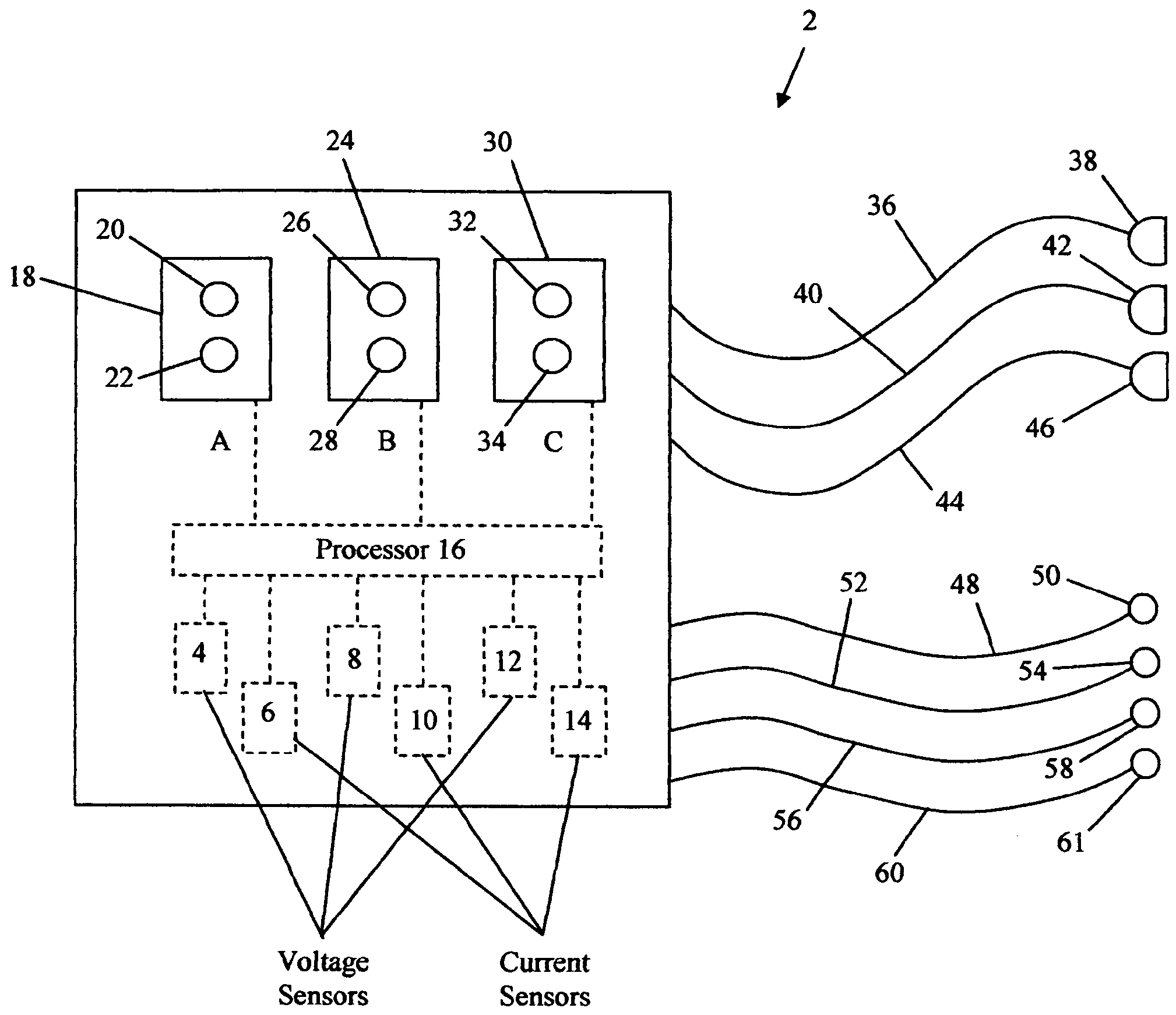
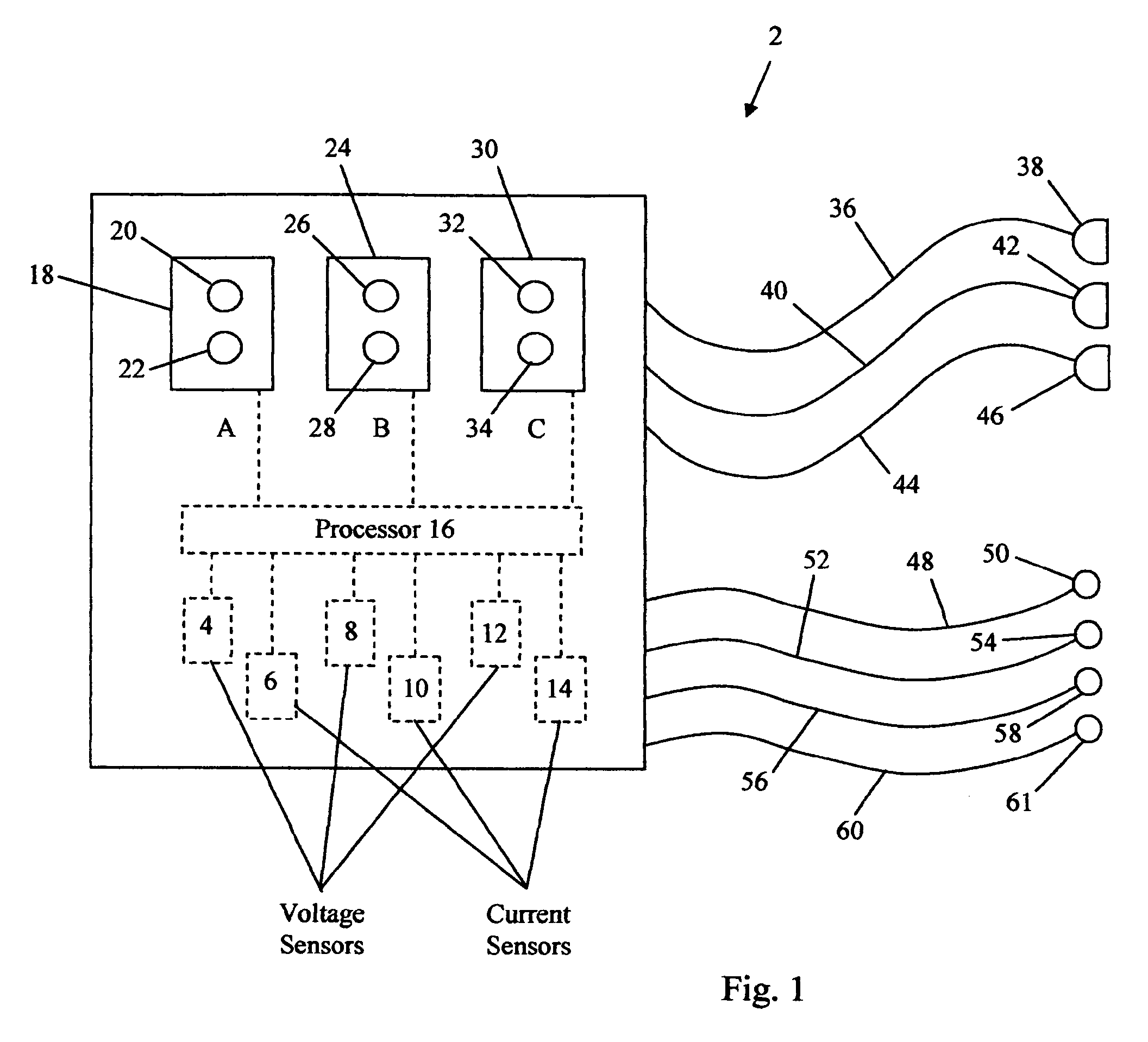
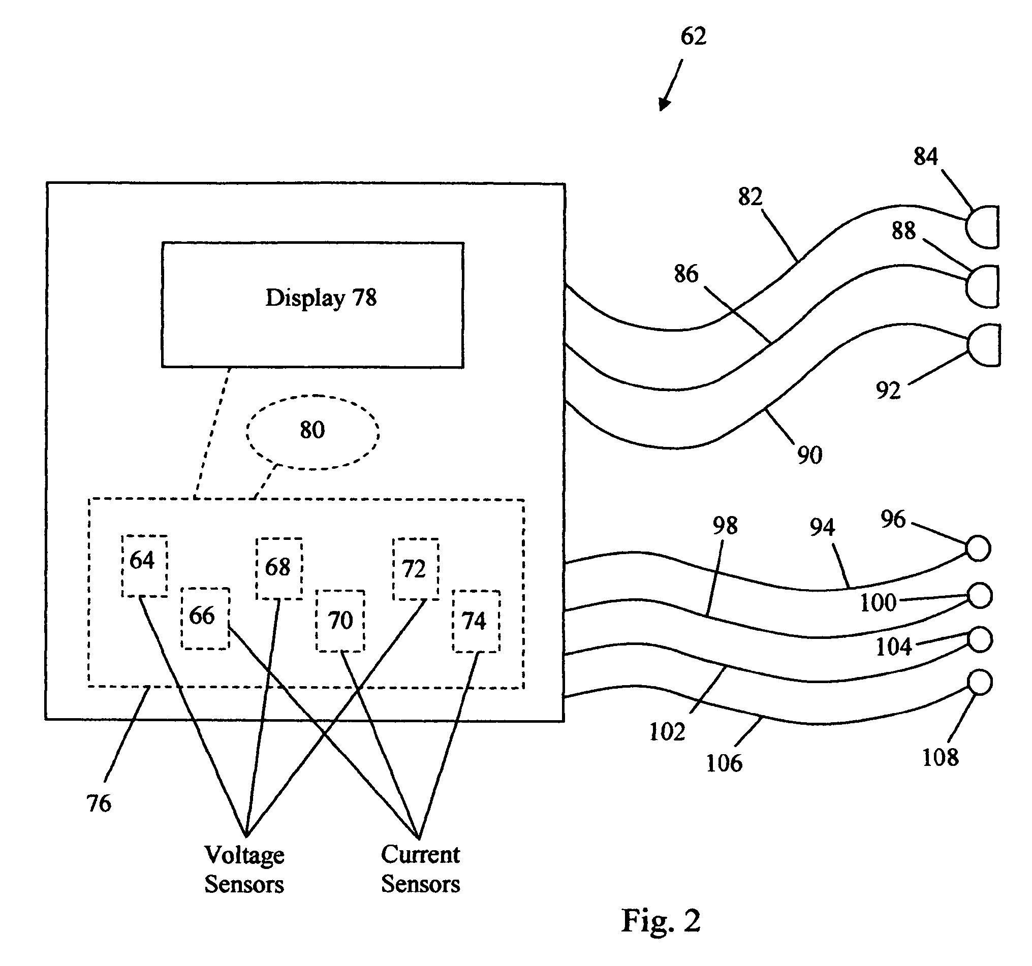
[0019]In one embodiment, this invention proposes the use of a testing algorithm built within the electrical meter together with six light emitting diodes (LEDs) in the form of three pairs of one red and one green LED. Each pair of LEDs may represent one of the phases and may light to indicate whether or not the CT phase matches the voltage phase for each of the three phases. In one embodiment, a green LED indicates correct matching, while a red LED indicates an error. The methodology can also be use on two-phase voltage systems (e.g., with only two bi-color LEDs) or on a three-phase, three-wire Delta service (typical for electric motors) which also requires only two CTs (even though there are three phases).

[0020]Several advantages of the present invention will be discussed below, with the un...


PUM


Abstract

An electrical phase checking apparatus includes a first voltage sensor, a first current sensor, a first binary indicator corresponding to the first voltage and current sensors, a second voltage sensor, a second current sensor, and a second binary indicator corresponding to the second voltage and current sensors. The first binary indicator is configured to indicate when a phase separation between a voltage waveform measured by the first voltage sensor and a current waveform measured by the first current sensor is not more than a first value, and the second binary indicator is configured to indicate when a phase separation between a voltage waveform measured by the second voltage sensor and a current waveform measured by the second current sensor is not more than a second value.

Description

BACKGROUND[0001]There is a growing interest in electrical energy metering in support of energy efficiency and conservation as well as bill reduction. Electrical power meters for both temporary and permanent installations have been used. Electrical power measurement often requires simultaneous measurement of both voltage and current (often using a sensor called a current transformer (“CT”) as a sensor) on one, two, or three electrical phases. Inside the meter the voltage is multiplied by the current (from the CT) to calculate watts, kilowatt-hours, and other electrical parameters.[0002]For two-phase and three-phase systems to be metered correctly, the phase of the wire the current sensor is placed on must match or correspond to the phase of the voltage that is measured and multiplied by the current to calculate watts.[0003]For a typical commercial or industrial electrical service, there are three phases: L1, L2, and L3 (though different designators can also be used). When metering a ...

Claims


Application Information

Patent Timeline
Patent Type & Authority Patents(United States)
IPC IPC(8): G01R19/00
CPCG01R25/005
Inventor DENT, CHRISTOPHER L.
Owner DENT INSTR INC
Why Eureka
Try Eureka