Magnetic recording disk and disk drive with patterned phase-type servo fields for read/write head positioning

a magnetic recording disk and phase-type technology, applied in the direction of maintaining head carrier alignment, digital recording, instruments, etc., can solve the problem of less than optimal signal-to-noise ratio (snr)

Inactive Publication Date: 2009-11-03
WESTERN DIGITAL TECH INC
View PDF18 Cites 21 Cited by
  • Summary
  • Abstract
  • Description
  • Claims
  • Application Information

AI Technical Summary

Problems solved by technology

However, because only a single polarity of magnetization is used with this method, half of the available signal amplitude from the servo islands is sacrificed and thus the signal-to-noise ratio (SNR) is less than optimum.

Method used


Image

  • Magnetic recording disk and disk drive with patterned phase-type servo fields for read/write head positioning
  • Magnetic recording disk and disk drive with patterned phase-type servo fields for read/write head positioning
  • Magnetic recording disk and disk drive with patterned phase-type servo fields for read/write head positioning

Examples


Embodiment Construction

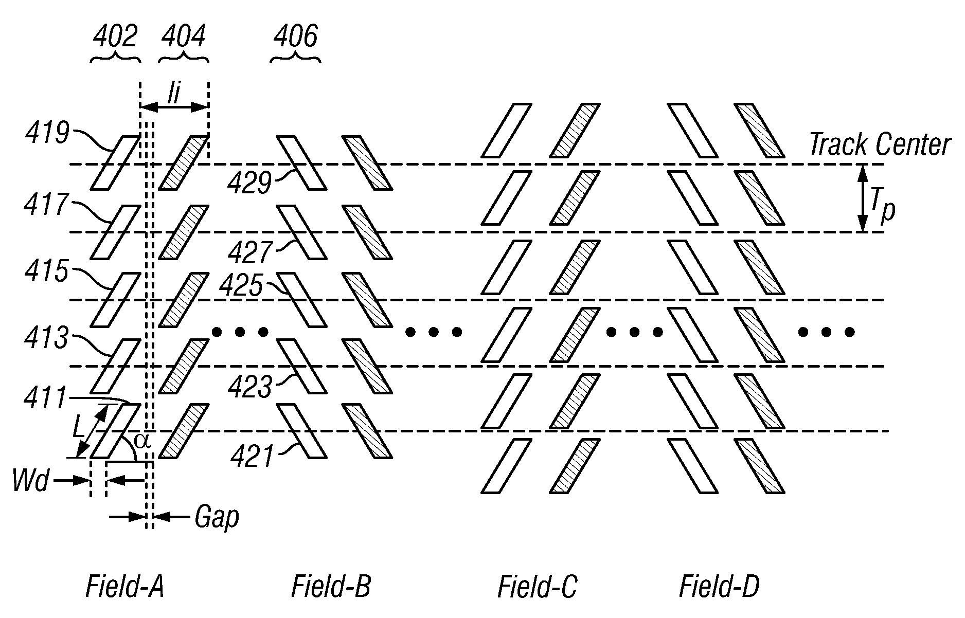
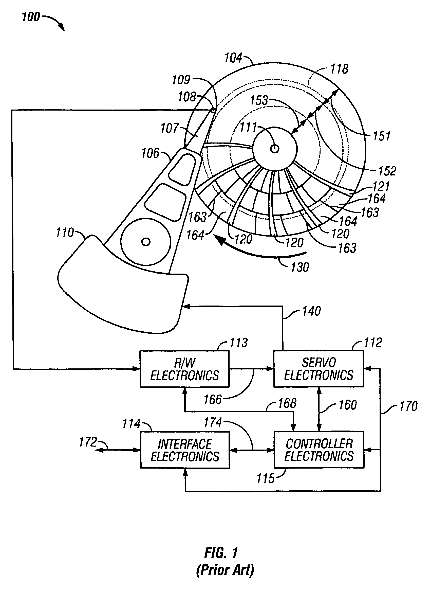
[0039]FIG. 1 is a schematic of a conventional magnetic recording disk drive and illustrates the magnetic recording disk with the nondata regions, specifically the servo sectors for positioning the recording heads on the data tracks and the synchronization fields for enabling the recording heads to read and write data in the data sectors. The disk drive, designated generally as 100, includes the magnetic recording disk 104, a voice coil motor (VCM) actuator 110, an actuator arm 106, a suspension 107, a head carrier or air-bearing slider 108 and a recording head 109. The recording head 109 is typically a combination of an inductive write head with a magnetoresistive read head (also called a read / write head) and is located on the trailing end or end face of slider 108. Slider 108 is supported on the actuator arm 106 by a suspension 107 that enables the slider to “pitch” and “roll” on an air-bearing generated by the disk 104 as it rotates in the direction of arrow 130. Only one disk sur...


PUM

PropertyMeasurementUnit
radial distanceaaaaaaaaaa
distanceaaaaaaaaaa

Abstract

A magnetic recording disk drive uses a disk having pre-patterned servo sectors extending generally radially across the data tracks. The servo sectors include at least two position error signal (PES) bursts or fields. The phases of the PES fields in the servo readback signal are demodulated to generate a PES to control the disk drive actuator for positioning the read / write heads. Each field contains generally radially directed magnetized stripes, with each stripe comprising a plurality of discrete radially-spaced generally parallelogram-shaped islands, each island having its length oriented at an acute angle relative to a track centerline. The stripes have alternating polarity of magnetizations in the along-the-track direction. In one implementation there are four fields: a first pair of fields A and B wherein the pattern of the radial stripes in field A is the mirror image about a radial line of the pattern of the radial stripes in field B, and a second like pair of fields C and D, but wherein the radial stripes in fields C and D are shifted radially from the radial stripes in fields A and B.

Description

RELATED APPLICATION[0001]This application is related to pending application Ser. No. 11 / 837,503 filed Aug. 11, 2007 and titled “MAGNETIC RECORDING DISK AND DISK DRIVE WITH PATTERNED PHASE-TYPE SERVO FIELDS FOR READ / WRITE HEAD POSITIONING”.BACKGROUND OF THE INVENTION[0002]1. Field of the Invention[0003]This invention relates generally to patterned-media magnetic recording disks, wherein each data bit is stored in a magnetically isolated data island on the disk, and more particularly to a patterned-media disk and disk drive with patterned nondata servo fields for head-positioning.[0004]2. Description of the Related Art[0005]Magnetic recording hard disk drives with patterned magnetic recording media have been proposed to increase the data density. In patterned media, the magnetic recording layer on the disk is patterned into small isolated data islands such that there is a single magnetic domain in each island or “bit”. The single magnetic domains can be a single grain or consist of a ...

Claims


Application Information

Patent Timeline
Patent Type & Authority Patents(United States)
IPC IPC(8): G11B5/09
CPCG11B5/59633G11B5/855G11B5/59688
Inventor YAMAMOTO, SATOSHI
Owner WESTERN DIGITAL TECH INC
Why Eureka
Try Eureka