Laminate flooring

a technology of laminate flooring and flooring panels, applied in the direction of flooring, walls, ceilings, etc., can solve the problems of time-consuming and messy installation of laminate flooring systems, not allowing the ready separation of flooring panels, and high difficulty in installation, so as to achieve greater resistance to disengagement of adjacent parts

Inactive Publication Date: 2009-11-10
WILSONART
View PDF168 Cites 205 Cited by
  • Summary
  • Abstract
  • Description
  • Claims
  • Application Information

AI Technical Summary

Benefits of technology

[0012]It is also an object of the present invention to provide an interlocking flooring system. The flooring system includes a plurality of flooring panels, each flooring panel including a plurality of edges. A first connecting member is provided for connecting adjacent flooring panels and a second connecting member is provided f

Problems solved by technology

Although these tongue and groove glue connections provided a sound flooring surface, the use of glue for bonding adjacent flooring panels made the installation of laminate flooring systems time consuming and messy.
For example, many of these systems, while providing a secure connection between adjacent flooring panels, do not permit the ready separation of flooring panels in the event it is necessary to remove all or a portion of the flooring surface in the event damage to the flooring surface necessitates the replacement of the flooring surface.
In addition, many connection systems require that the flooring panels be positioned in awkward configurations during the installation process, making it time consuming and highly difficult to complete installation when the flooring panels are installed in tight or irregular spaces.
In addition to the problems associated with the installation of decorative laminate flooring systems, those skilled in the art will appreciate the various problems encountered even after the fl

Method used


Image

  • Laminate flooring
  • Laminate flooring
  • Laminate flooring

Examples


Embodiment Construction

[0034]The detailed embodiments of the present invention are disclosed herein. It should be understood, however, that the disclosed embodiments are merely exemplary of the invention, which may be embodied in various forms. Therefore, the details disclosed herein are not to be interpreted as limited, but merely as the basis for the claims and as a basis for teaching one skilled in the art how to make and / or use the invention.

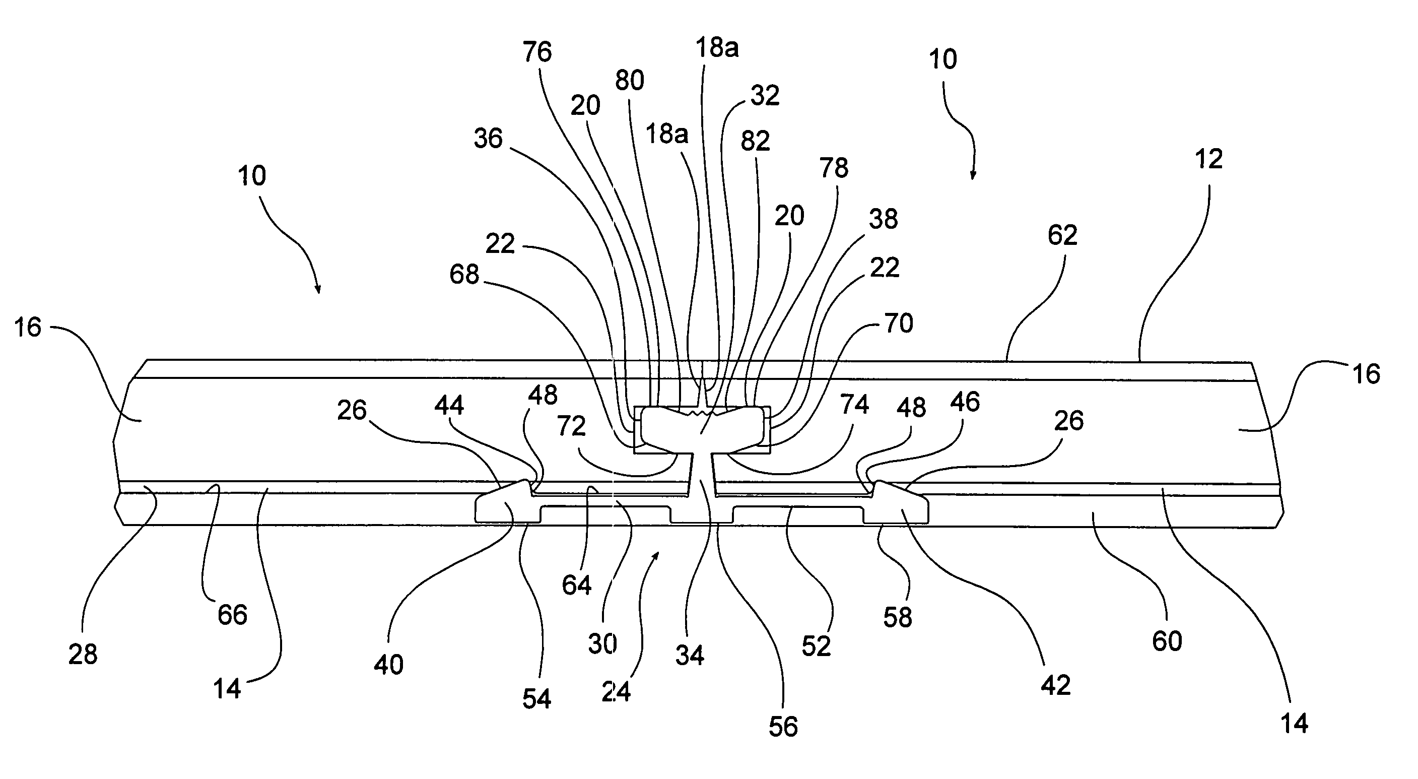
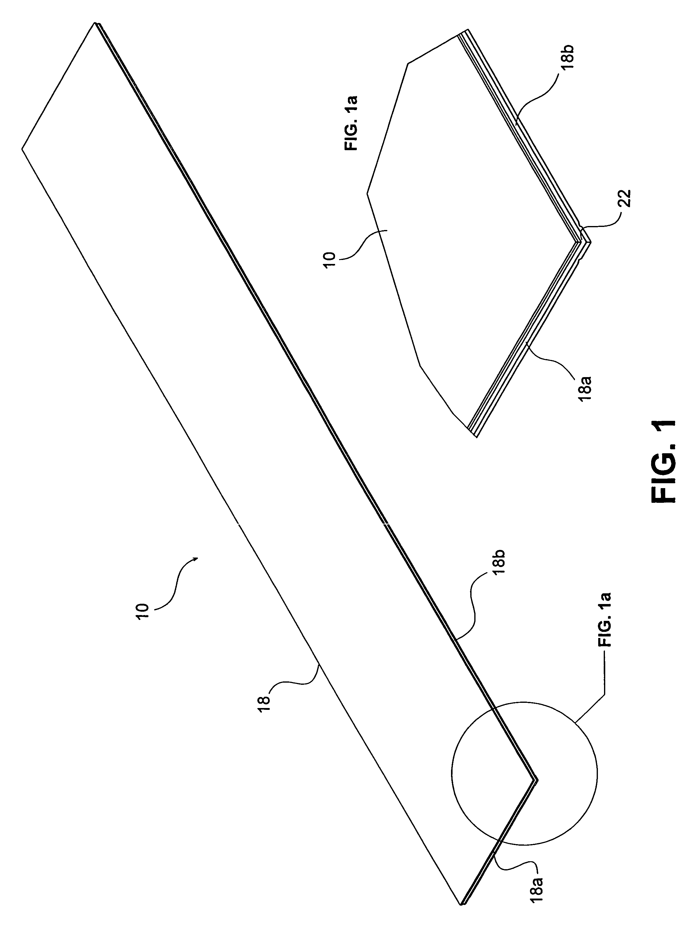
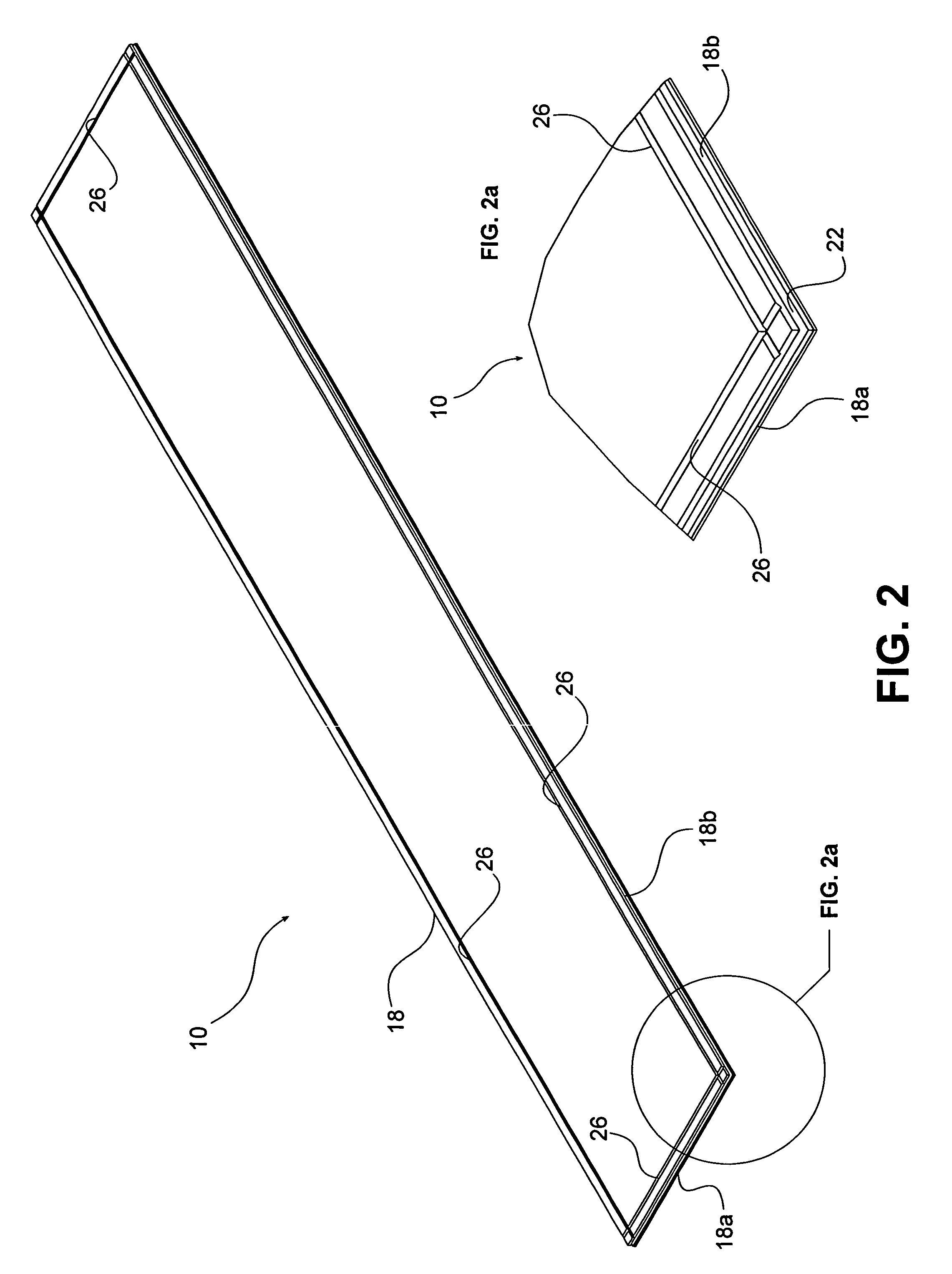
[0035]With reference to FIGS. 1, 1a, 2, 2a, 3, 4 and 5, a decorative laminate flooring panel 10 used in conjunction with present connection system is disclosed. The decorative laminate flooring panel 10 generally includes a decorative surfacing layer 12 (or decorative laminate), a backing layer 14 and a substrate 16, more particularly, corestock positioned between the decorative surfacing layer 12 and the backing layer 14. The edge 18 of the flooring panel 10 includes an outwardly facing, interlocking profile 20 shaped and dimensioned for selective attachment to a...


PUM


Abstract

A disengageable connector for interconnecting panels includes a longitudinally extending connector body. The connector body including a base and a projection extending from the base. The base includes a top surface and a bottom surface, and at least one footing member extending downwardly from the bottom surface of the base. The footing member is shaped and dimensioned to compress the upper surface of a resilient pad positioned beneath the connector and the panels. The connector is used in conjunction with an interlocking flooring system. The interlocking flooring system includes a plurality of flooring panels, each flooring panel including a plurality of edges. A first connecting member is provided for connecting adjacent flooring panels and a second connecting member is provided for connecting adjacent flooring panels. The first connecting member is the same as the connector described above and is different from the second connecting member. The first connecting member provides greater resistance to disengagement of adjacent flooring panels when compared to the second connecting member.

Description

RELATED APPLICATIONS[0001]The present application is a continuation-in-part of U.S. patent application Ser. No. 09 / 941,500, filed Aug. 29, 2001 now abandoned, and entitled “Interconnecting Disengageable Flooring System”, and which is a divisional of U.S. patent application Ser. No. 09 / 436,317, filed Nov. 8, 1999, and entitled “Interconnecting Disengageable Flooring System”, which is currently U.S. Pat. No. 6,460,306. The present application is also a continuation-in-part of U.S. patent application Ser. No. 10 / 265,900, filed Oct. 7, 2002 now U.S. Pat. No. 6,769,217, and entitled “Interconnecting Disengageable Flooring System”, and which is a continuation of U.S. patent application Ser. No. 09 / 436,317, filed Nov. 8, 1999, and entitled “Interconnecting Disengageable Flooring System”, which is currently U.S. Pat. No. 6,460,306.BACKGROUND OF THE INVENTION[0002]1. Field of the Invention[0003]The invention relates to decorative laminate flooring panels. More particularly, the invention rel...

Claims


Application Information

Patent Timeline
IPC IPC(8): E04B2/00E04F15/04
CPCE04F15/04E04F2201/05E04F2015/0205
Inventor NELSON, THOMAS J.
Owner WILSONART
Why Eureka
Try Eureka