Channel gun magnetic launcher

a magnetic launcher and channel gun technology, applied in the direction of weapons, white arms/cold weapons, weapons, etc., can solve the problems of large and rapid wear of rails, difficult to use, and many rail guns can only be used for a single application or a small number of applications, so as to achieve not tremendously heated and destroyed, simple structure, and the effect of not wasting energy

Inactive Publication Date: 2009-11-10
LU WEIMIN
View PDF20 Cites 35 Cited by
  • Summary
  • Abstract
  • Description
  • Claims
  • Application Information

AI Technical Summary

Benefits of technology

[0017]According to a first aspect and feature of the present invention an electromagnetic launcher is provided for use in accelerating a projectile to hypervelocity (a velocity approximately 3,000 meters per second or greater), the electromagnetic launcher comprising: an electric power supply; a conductive, stationary guide operatively connected to the power supply and forming a flowpath for current from the power supply; and a non-conductive projectile disposed adjacent to the guide and which is accelerated along the guide when current flows through the guide, the guide including a plurality of conductive rails disposed in spaced, substantially parallel relation to each other, a plurality of conductive rungs interconnecting the rails and disposed in spaced relation to each other along the rails, and normally-open switches operatively associated with the rungs for selectively permitting current flow through different ones of the rungs. The projectile of the electromagnetic launcher includes a main body and a magnet supported by the main body such that the magnet faces the guide with a small gap therebetween. The switches are passively and automatically activated only when they are disposed within a magnetic field of the projectile, such that the switches are sequentially activated as the projectile moves along the guide and creates an electromagnetic pushing force which continuously accelerates the projectile along the guide substantially in a direction parallel to the guide.
[0018]The electromagnetic launcher according to the first aspect and feature of the present invention is very advantageous over conventional launchers such as rail guns and coil guns, and desirably combines favorable characteristics of the prior launchers, without the attendant disadvantages. For example, the projectile of the present invention is non-conductive and does not form part of the current flow path with the power supply and the guide, unlike in a rail gun where the current flows through the conductive projectile, as well as through the rail. Thus, the non-conductive projectile is not forced into electrical contact with the guide, but moves parallel to the guide with little or no physical contact therebetween, and there is no electric arcing on the projectile, such that the guide is not tremendously heated and destroyed each time a projectile is launched. Unlike conventional rails guns wherein the guide can only be used for a single or small number of launches due to the heat and destruction caused during a launch, the guide of the launcher according to the present invention may be reused repeatedly for launching many projectiles.
[0019]As another example, only one or a small number of the guide rungs are directly adjacent to the projectile at any given time and such that the switch(es) associated therewith are activated to permit current flow through the rungs. Thus, the launcher according to the present invention may be considered to have essentially only one turn for the current flowing from the power supply and through the guide at any given time. Correspondingly, there is minimum inductance associated with the launcher/guide, unlike the conventional coil gun which has substantial inductance associated therewith, such that the switc

Problems solved by technology

While rail guns are in principle very simple, they have several known disadvantages, making them practically difficult.
One known disadvantage is that, since the projectile must be in constant physical contact and electrical conductivity with the rails to let electric current flow as the projectile is being launched, large amounts of heat are generated between the moving projectile and the rails which burns the rails thereby causing significant and rapid wear of the rails.
Thus, many rail guns can only be used for a single application or a small number of applications due to the damaged to the rails.
However, while plasma arcing allows for the projectile to not come directly into contact with the rails, a rail gun using a plasma armature generates an even higher amount of heat than a conventional rail gun, again, damaging the rails.
Another disadvantage of using a rail gun is that rail guns require an extremely high current DC power source.
Further, the extremely high current is required to be generated over a very short period of time.
Without such a high current generated over such a short period of time, the projectile would fail to be launched at an appropriate velocity.
Thus, a pow

Method used


Image

  • Channel gun magnetic launcher
  • Channel gun magnetic launcher
  • Channel gun magnetic launcher

Examples


example 1

[0058]As an example of the embodiment shown in FIG. 4, in calculations with an extended length for the electric ladder and without accounting for air friction, if the conductive rungs are spaced approximately one-eighth (⅛) of an inch apart the switches 20 are capable of being activated and deactivated by the controller 17 at 1 MHz. If the length of the projectile is then set at one (1) inch, a muzzle velocity of the projectile can reach approximately 16,000 miles per hour (mph) or 7 kilometers per second (kmps), which gives the projectile enough kinetic energy to launch it out to space, for example. With such a configuration, each switch may be a 1 MHz MOSFET switch that can easily be activated from the front end of the projectile and can easily be deactivated by the rear end of the projectile. Thus, if the total time which the switch would be activated is 3.6 μs for the one (1) inch projectile to travel, the speed of the projectile would be 1,000,000 / 3.6*1=277,778 inches per secon...

example 2

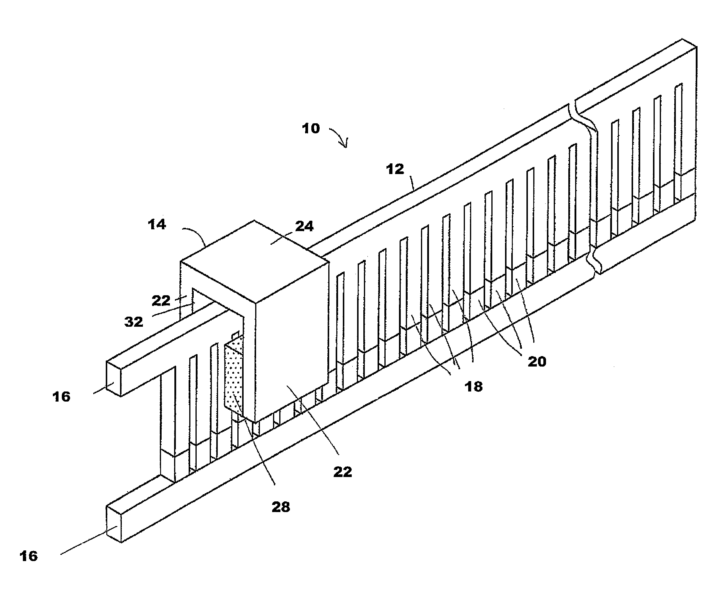
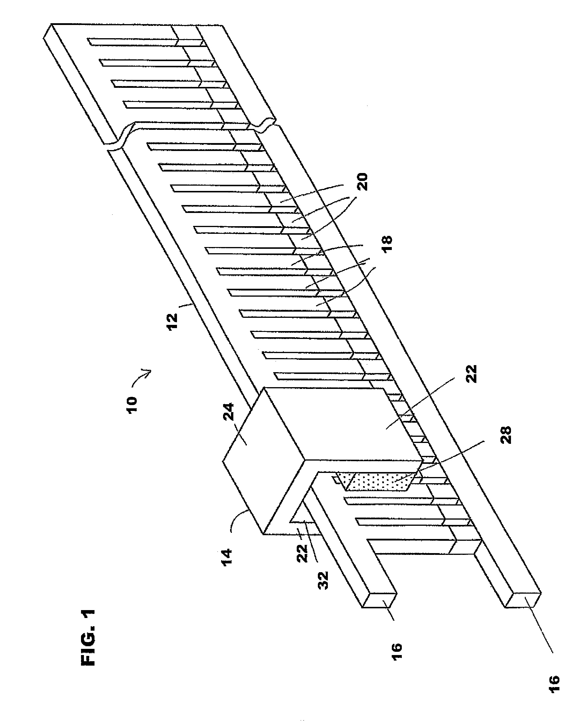
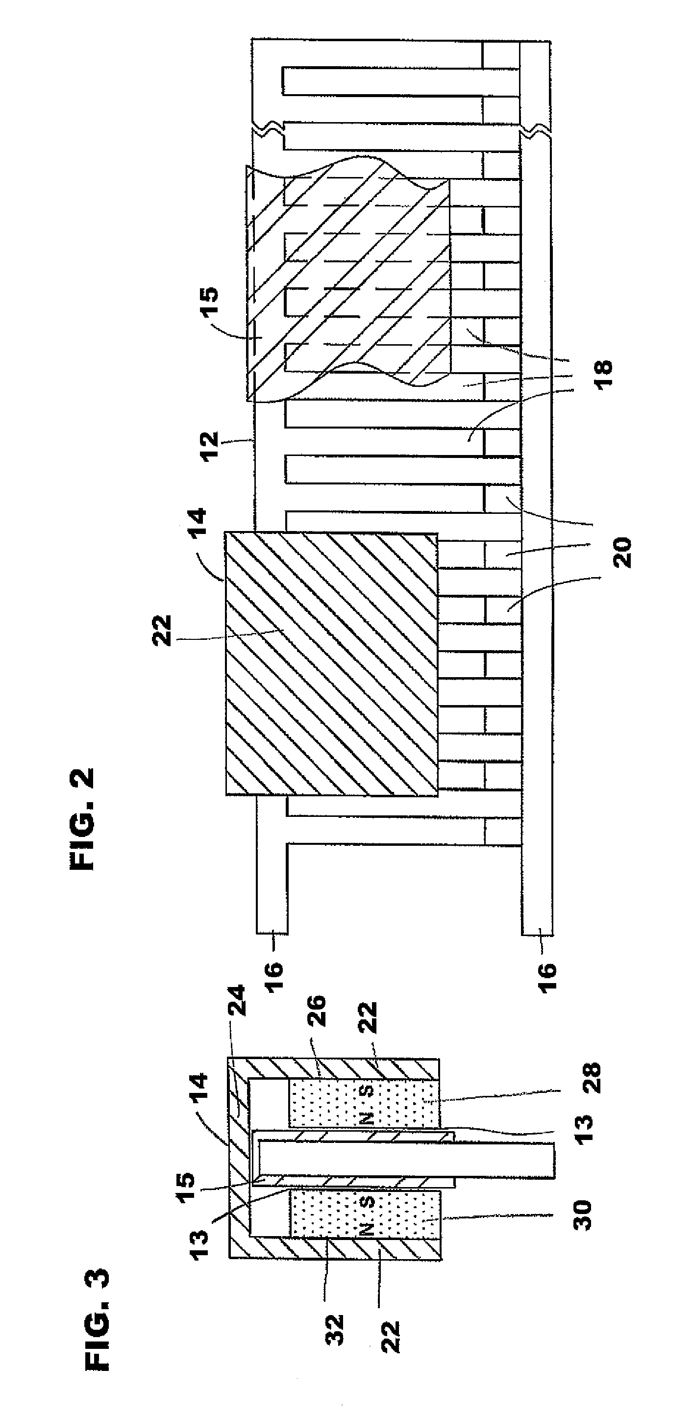
[0059]As en example of the embodiment described above in FIGS. 1-3 and 5, in an ideal scenario wherein there is no friction, the magnetic force F can be calculated using the Lorentz equation, which is reformatted below as Equation B, in SI units,

F=L*I*B  (Equation B)

wherein the magnetic force (F) is measured in Newtons, the length (L) is measured in meters, the current force (I) is measured in amperes, and the magnetic inductance force (B) is measure in Tesla. If in the single turn ladder structure of the first illustrative embodiment, as shown in FIGS. 1-3 and 5, there is a 0.1 meter long Neodymium-iron-born (NIB) magnet with 1 Tesla magnetic field strength, applying 5,000 Amps DC current going through, then: F=L*I*B=0.1*5,000*1=500 Newtons. If the projectile weighs 1 kg, then the acceleration force (A)=Force / mass (F / m)=500 / 1=500 meters per second squared. Thus if the projectile's beginning velocity is zero, then after one (1) second, the velocity after one (1) second=Acceleration*...

example 3

[0060]As an example of the embodiment described above in FIG. 20, if instead of the single turn ladder structure of the first illustrative embodiment, we have a the looped conductive rung ladder structure, such as that shown in FIG. 20, and there is a 20-turn loop per rung structure, a 0.1 meter long Neodymium-iron-born (NIB) magnet with 1 Tesla magnetic field strength, and applying 5,000 Amps DC current going through, then the calculations work out as follows: F=L*I*B=(20*0.1)*5,000*1=10,000 Newtons. If the projectile weighs 1 kilogram, then the acceleration force (A)=Force / mass (F / m)=10,000 / 1=10,000 meters per second squared. Then in order to reach the muzzle speed of 7,000 meters per second, it will take 0.7 seconds. If we are using an elongate electric ladder, the length of the ladder would be S=½ Acceleration*time2(½A*t2)=½*10,000*0.72=2500 meters or 2.5 km.

[0061]While the above-described embodiments of an electromagnetic launcher according to the invention include a guide with...


PUM


Abstract

An electromagnetic launcher comprising, an electric power supply, a conductive, stationary guide operatively connected to the power supply and forming a flowpath for current from the power supply, and a non-conductive projectile disposed adjacent to the guide and which is accelerated along the guide when current flows through the guide. The guide includes a plurality of conductive rails disposed in spaced, substantially parallel relation to each other, a plurality of conductive rungs interconnecting the rails and disposed in spaced relation to each other along the rails, and normally-open switches operatively associated with the rungs for selectively permitting current flow through different ones of the rungs. The projectile includes a main body and a magnet supported by the main body such that the magnet faces the guide with a small gap therebetween. The switches are passively activated only when they are disposed within a magnetic field of the projectile, such that the switches are sequentially activated as the projectile moves along the guide and create an electromagnetic pushing Lorentz force which continuously accelerates the projectile along the guide substantially in a direction parallel to the guide.

Description

BACKGROUND OF THE INVENTION[0001]1. Field of the Invention[0002]The present invention relates to an electromagnetic projectile launcher, and in particular, to an electromagnetic projectile launcher wherein the projectile is continuously accelerated to a high velocity in a very efficient manner involving minimal physical contact and essentially no electrical conductivity between the launcher and the projectile.[0003]2. Description of the Background Art[0004]Known electromagnetic accelerators have been designed to accelerate and launch projectiles at high velocities. An example of such an electromagnetic accelerator is a rail gun, which consists of parallel conductive sliding or rolling rails and a conductive projectile riding along such conductive rails, which together form a closed electrical circuit. When the parallel conductive rails are connected to a power supply, the conductive sliding or rolling rails allow a large electric current to pass through the projectile. Electric curr...

Claims


Application Information

Patent Timeline
IPC IPC(8): F41B6/00
CPCF42B6/006F41B6/006
Inventor LU, WEIMIN
Owner LU WEIMIN
Why Eureka
Try Eureka