Radar level gauge with variable pulse parameters

a pulse parameter and radar technology, applied in the direction of engine lubrication, liquid/fluent solid measurement, reradiation, etc., can solve the problem that pulse radars typically have lower sensitivity than frequency modulated continuous wave radars, and achieve optimized pulse width selection, optimized balance, and optimized map resolution and sensitivity.

Active Publication Date: 2010-09-21
ROSEMOUNT TANK RADAR
View PDF12 Cites 16 Cited by
  • Summary
  • Abstract
  • Description
  • Claims
  • Application Information

AI Technical Summary

Benefits of technology

[0014]By means of this pulse width adjustment, it becomes possible to obtain an optimized balance between signal strength of the received reflected signals and the ability of detecting relatively weak reflections on the one hand, and resolution between different reflected signals on the other hand. The theoretical background for this is explained in more detail in the following. Hence, the present invention is particularly advantageous for applications where several levels are to be measured, e.g. due to several different material interfaces in the tank.
[0015]The present invention e.g. enables automated production tests, since the pulse width can be changed during operation, without specific tools etc. Further, the pulse width adjustment functionality can be used in a system where the pulse width is continuously controlled in order to achieve an optimized map of resolution and sensitivity, and for obtain an optimized choice of the pulse width. For example, this allows targets of interest that provide weak echoes to be emitted with more energy, and vice versa. Targets that are close in terms of distances, can be better distinguished if the pulse width is shortened. In accordance with the invention, the system functionality can be made adaptive, in order to obtain an optimized resolution / sensitivity at all times, and for all types of application conditions.
[0016]Thus, one advantageous way of using the present invention is to provide an easy adaptation of the pulse width of a general radar level gauge system to a known measuring situation, wherein fixed settings may be used.

Problems solved by technology

However, pulsed radars typically have lower sensitivity compared to frequency modulated continuous wave (FMCW) radar.

Method used


Image

  • Radar level gauge with variable pulse parameters
  • Radar level gauge with variable pulse parameters
  • Radar level gauge with variable pulse parameters

Examples


Embodiment Construction

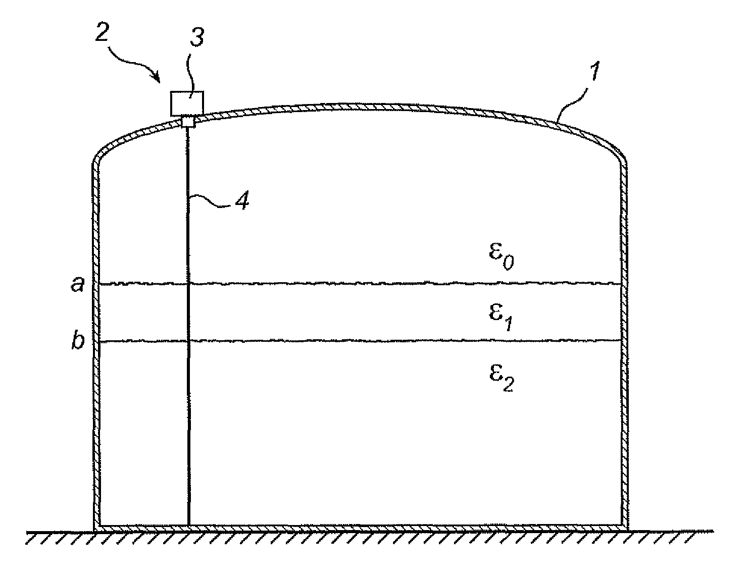
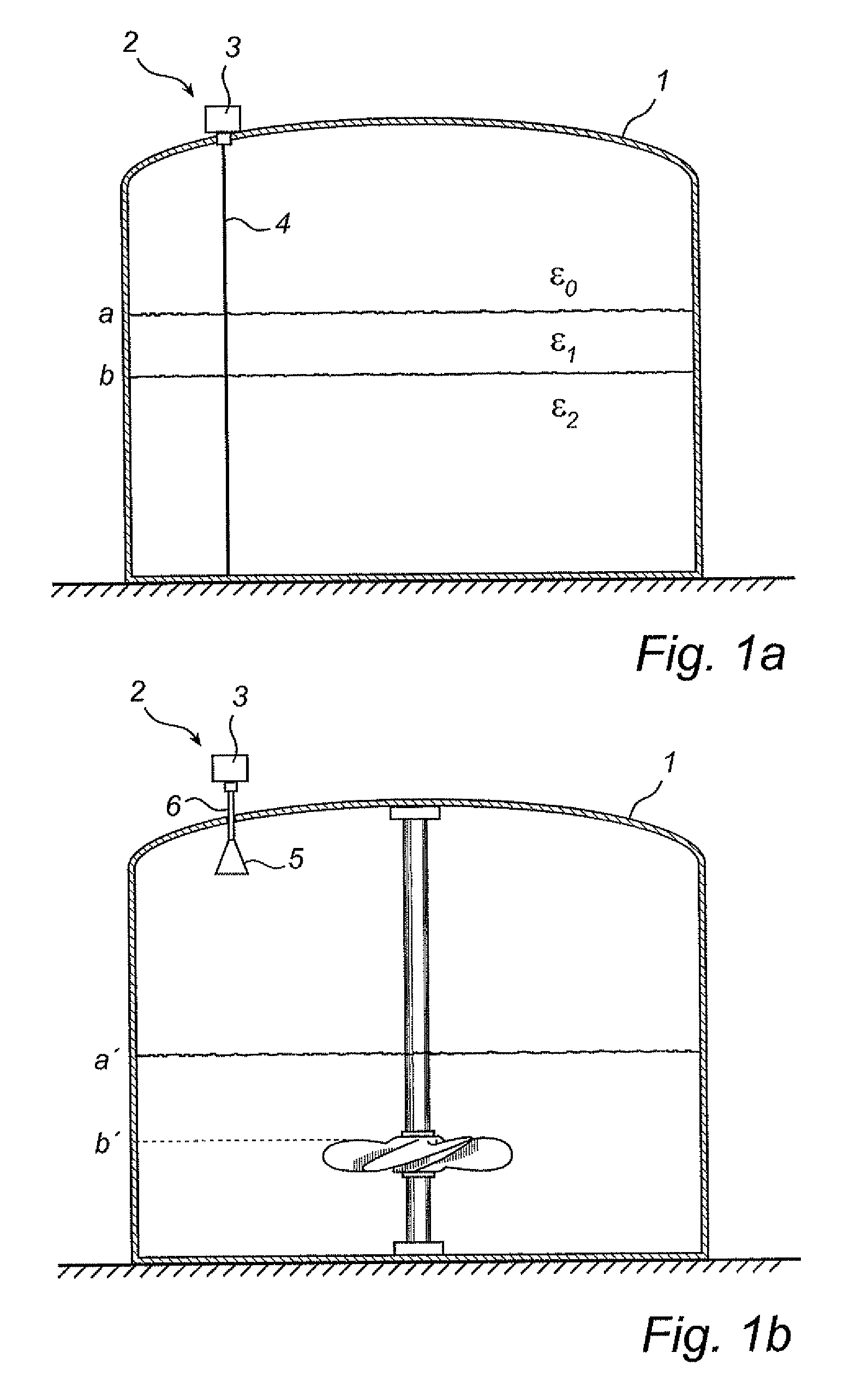
[0036]FIGS. 1a and 1b show schematically a radar level gauge (RLG) system 2 according to the present invention. As is discussed in more detail in the following, the radar level gauge system comprises an electronic unit 3 for transmitting and receiving radar signals and processing the received signals in order to determine the level of a filling material in the tank 1. Specifically, the system 2 is arranged to perform measurements of one or several level of a filling material, such as the level of an interface between two (or more) materials in the tank. Typically, the first material is a content stored in the tank, e.g. a liquid such as gasoline, while the second material is air or some other atmosphere. In that case, the RLG will enable detection of the level of the surface of the content in the tank. Notably, different tank content have different impedance, and the electromagnetic waves will not propagate through any material in the tank. Typically, therefore, only the level of a ...


PUM


Abstract

A radar level gauge (RLG) system and method for determining a filling level of a filling material in a tank is disclosed. The RLG system comprises a transmitter for generating and transmitting an electromagnetic transmitter pulse signal, a transmitter controller for controlling means for pulse width adjustment for adjusting the pulse width of the transmitter pulse signal in dependence of at least one application specific condition. Further, the system comprises a signal medium interface connectable to means for directing said transmitter pulse signal towards said filling material and for receiving a reception pulse signal reflected back from said filling material; a receiver for receiving said reception pulse signal from the tank; and processing circuitry for determining the filling level of the tank based on said reflection pulse signal received by said receiver. The application specific condition(s) is e.g. one or several of tank height, level of the filling material, type of filling material, presence of other tank structure providing reflecting surfaces and required accuracy of measurement.

Description

FIELD OF THE INVENTION[0001]The present invention relates to a pulsed radar level gauge system and a corresponding method.BACKGROUND OF THE INVENTION[0002]Radar level gauging (RLG) to measure the level of a filling material, such as a liquid or a solid like a granulate is an increasingly important method for level gauging in tanks, containers, etc. In RLG, continuously emitted radiation, and in particular FMCW, is used for most applications. However, pulsed RLG is becoming a more widely spread method for industrial level gauging, due to its simple and cost effective microwave components. The pulse in a pulsed RLG can be modulated by a carrier frequency, typically 6 or 24 GHz, or be an unmodulated DC pulse. In the latter case, it is common to use some kind of transmission line, such as a coaxial line, twin line, etc., sometimes referred to as a probe, in order to guide the electro-magnetic signal through the material in the tank where it is reflected by one or more interface surfaces...

Claims


Application Information

Patent Timeline
Patent Type & Authority Patents(United States)
IPC IPC(8): G01F23/284G01S13/08
CPCG01F23/284G01F25/0061G01S7/282G01S13/106G01S13/88G01F25/20
Inventor NILSSON, VALTERJIRSKOG, ANDERSPENNDAL, NIKLAS
Owner ROSEMOUNT TANK RADAR
Why Eureka
Try Eureka