Thermal insulation for a bonding tool

a bonding tool and thermal insulation technology, applied in the direction of manufacturing tools, soldering devices, auxiliary welding devices, etc., can solve the problems of affecting the accuracy of wire bonding, and the ineffective use of conventional thermal shields in the wire bonding system, so as to reduce the amount of heat and minimize any thermal expansion.

Active Publication Date: 2009-11-10
ASM TECH SINGAPORE PTE LTD
View PDF5 Cites 2 Cited by
  • Summary
  • Abstract
  • Description
  • Claims
  • Application Information

AI Technical Summary

Benefits of technology

[0012]It is thus an object of this invention to seek to reduce the amount of heat being transferred to a bonding tool from external heat sources so as to minimize any thermal expansion experienced by the bonding tool.

Problems solved by technology

As a result, wire bonding accuracy is affected.
For the aforesaid reasons, use of a conventional thermal shield in a wire bonding system does not effectively address the problem of thermal instability encountered by a transducer during wire bonding.

Method used


Image

  • Thermal insulation for a bonding tool
  • Thermal insulation for a bonding tool
  • Thermal insulation for a bonding tool

Examples


Embodiment Construction

[0023]The preferred embodiment of the present invention will be described hereinafter with reference to the accompanying drawings.

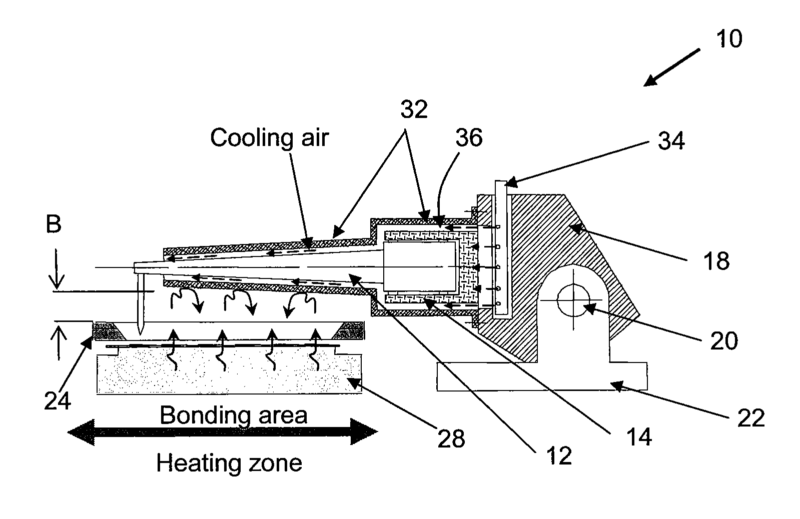
[0024]FIG. 5 is a side view of a wire bonding apparatus 10 with a bonding tool such as a transducer 12 and a transducer holder 14 substantially enclosed within a thermal shield 32 according to the preferred embodiment of the invention. The transducer 12 is mounted to the bond arm 18 by way of the transducer holder 14 of the bond arm 18. The thermal shield 32 may be made from any insulating material, such as plastic, which provides suitable heat insulation of the transducer 12 from ambient heat during wire bonding. A substantial length of the transducer 12 is encircled by the thermal shield 32, generally leaving uncovered only a tip end of the transducer 12 where the capillary 16 is located. By substantially enclosing the transducer 12 and transducer holder 14, the thermal shield 32 reduces heat radiation from the heater block 28 being received directly by...


PUM

PropertyMeasurementUnit
heat insulatingaaaaaaaaaa
insulatingaaaaaaaaaa
shapeaaaaaaaaaa

Abstract

A bonding apparatus comprising a bond arm and a wire bonding tool mounted to the bond arm is provided with thermal insulation in the form of a thermal shield substantially enclosing the bonding tool for insulating the bonding tool from ambient heat.

Description

FIELD OF THE INVENTION[0001]The present invention relates to thermal insulation of a bonding tool, such as a wire bonding tool, to protect the bonding tool from external heat sources during operation thereof.BACKGROUND AND PRIOR ART[0002]Wire bonding is typically applied to make electrical connections between an integrated circuit die or chip and a carrier on which the die is mounted. Bonding wires are attached to bond pads on the chip and bonding leads on the carrier respectively by ultrasonic welding using an ultrasonic transducer which is integrated into a wire bonding apparatus. The ultrasonic transducer is an energy converting-device which converts electrical energy into ultrasonic vibrations and transmits the ultrasonic vibrations to a capillary at a tip end of the transducer to perform wire bonding.[0003]FIG. 1 illustrates a side view of a conventional wire bonding apparatus 10 with a transducer 12 positioned over a bonding area for wire bonding. The transducer 12 has a long ...

Claims


Application Information

Patent Timeline
Patent Type & Authority Patents(United States)
IPC IPC(8): B23K1/06B23K37/00
CPCB23K20/004H01L24/78H01L2224/78301H01L2224/78823H01L2924/14H01L2924/3025Y10S228/904H01L2924/00014H01L2224/48H01L2224/45099H01L2224/05599
Inventor KWAN, KA SHING KENNYYEAP, BOON JUNE
Owner ASM TECH SINGAPORE PTE LTD
Why Eureka
Try Eureka