Attachment device for fixing various elements to a support

a technology of fixing device and supporting, which is applied in the direction of building scaffolds, candle holders, ceilings, etc., can solve the problems of mechanical strength of the attachment, and achieve the effect of high mechanical strength and no risk of tear-o

Active Publication Date: 2009-11-10
A RAYMOND & CO
View PDF19 Cites 41 Cited by
  • Summary
  • Abstract
  • Description
  • Claims
  • Application Information

AI Technical Summary

Benefits of technology

[0008]The object of the invention consists in remedying the above-mentioned drawbacks, and in providing an attachment device with a high mechanical strength, able to manage several thicknesses of the support, without requiring the use of assembly tools and specific accessories for fixing the elements, and able to support large suspended weights without any risk of tear-off.
[0010]The spigots digging into the top face of the support and the spring effect of the two flexible teeth enhance the holding strength by opposing any sliding movement of the part in the inserted position. The two flexible teeth coming into contact against the bottom face of the support enable several thicknesses of the support to be managed.

Problems solved by technology

This type of known attachment has the following drawbacks:use of a tool (spanner or screwdriver) to perform efficient tightening of the screw onto the support;reduced mechanical strength of the attachment due to the leverage effect created by the screw when tightening is performed;compulsory use of fixing accessories when the elements are formed by threaded or smooth rods, collars, plastic straps, small chains, cables, etc.

Method used


Image

  • Attachment device for fixing various elements to a support
  • Attachment device for fixing various elements to a support
  • Attachment device for fixing various elements to a support

Examples


Embodiment Construction

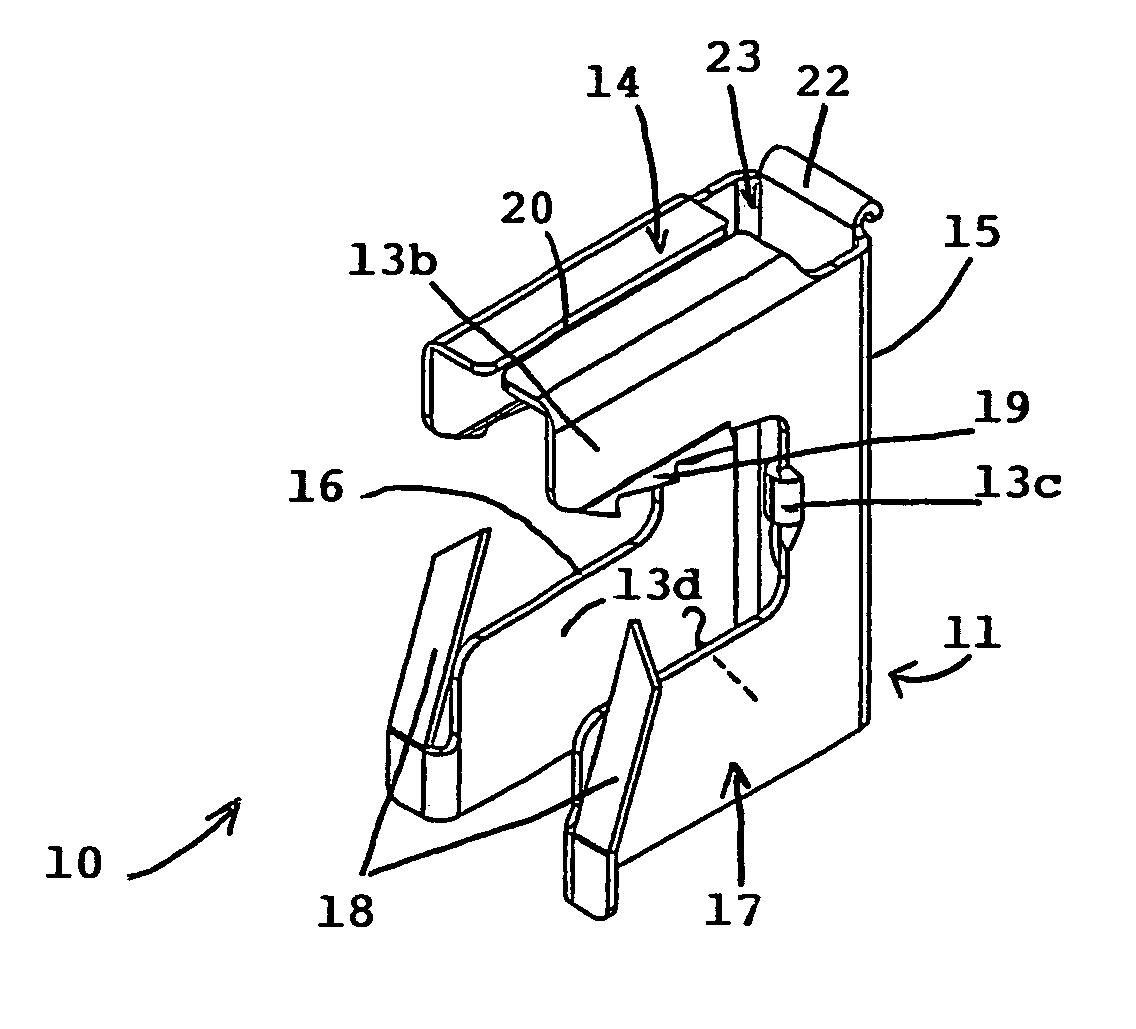
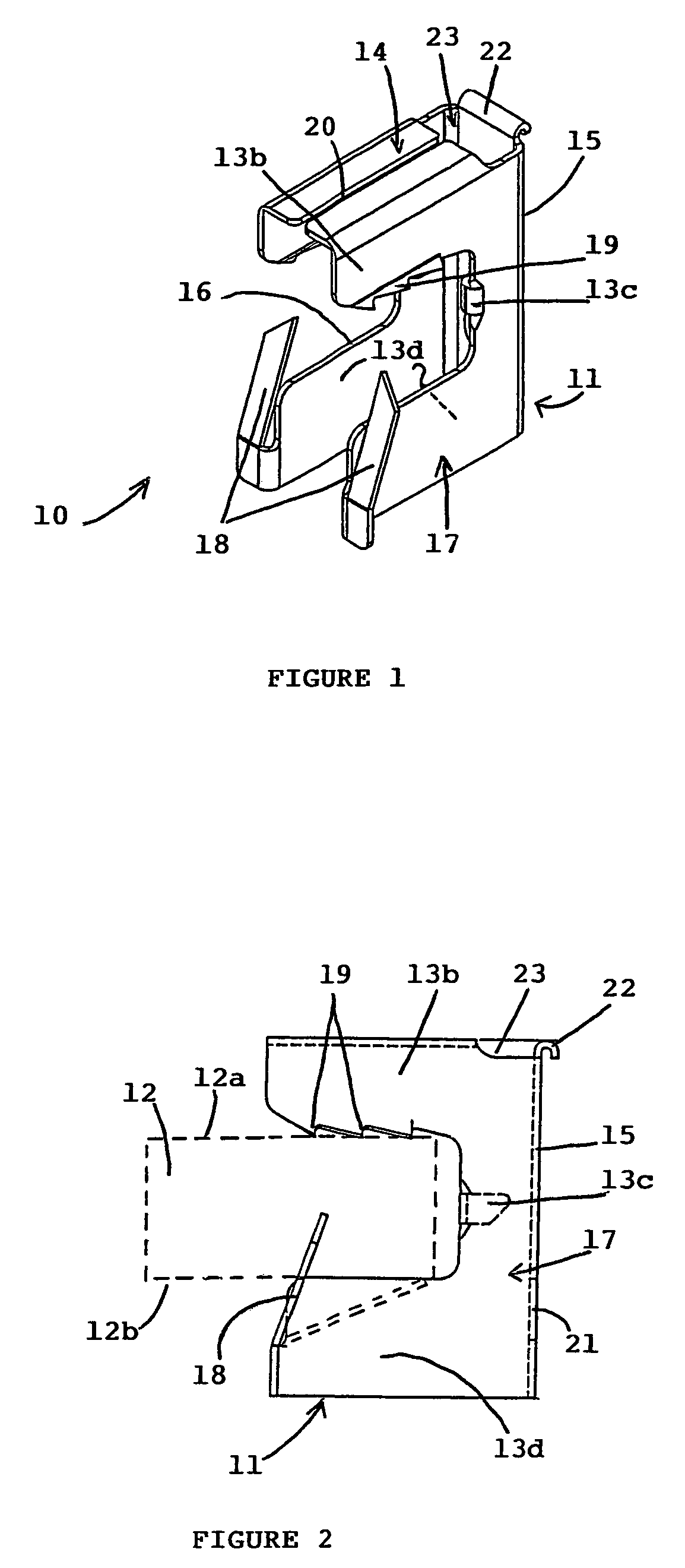
[0032]With reference to FIGS. 1 to 5, an attachment device 10 comprises a metal part 11 shaped as a rider to be fitted edgewise onto a support 12 so as to enable suspension or fixing of various elements. The support 12 (represented schematically by broken lines in FIG. 2) is formed for example by a straight metal beam or bar of rectangular cross-section having two flat parallel opposite faces 12a, 12b.

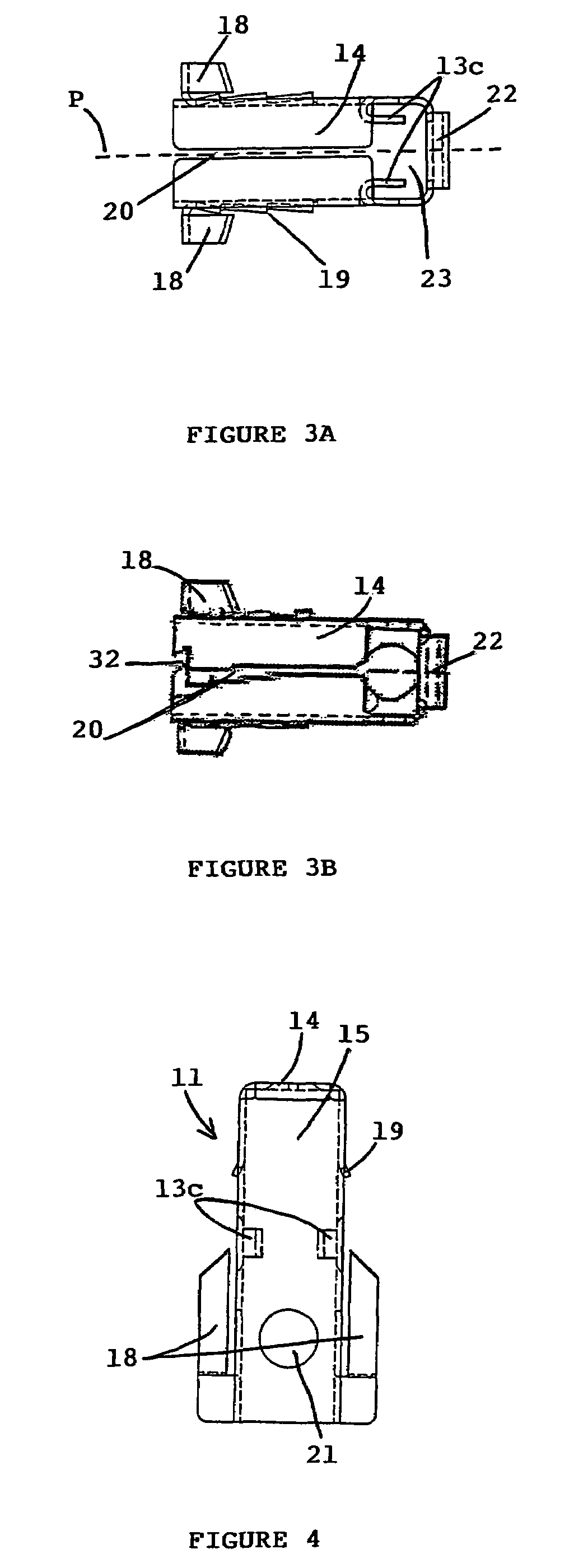
[0033]The metal part 11 is obtained by cutting a metal plate 13 or sheet having a small thickness. Cutting is performed according to an outline represented in FIG. 5, which presents a double E-shaped structure symmetrical with respect to the vertical mid-plane of symmetry P. The double E-shaped structure is composed of a common body 13a provided on each side thereof with two top arms 13b, two intermediate tabs 13c and two bottom arms 13d.

[0034]The metal plate 13 is then folded around several folding lines to achieve the metal part 11 (FIG. 1) of the attachment device 10.

[0035]The fol...


PUM


Abstract

An attachment device comprises a metal part obtained by cutting and folding a metal plate or sheet, and shaped as a rider designed to be fitted astride a metal support in the form of a beam or a bar. The metal part comprises a U-shaped flange having two side faces forming a jaw equipped with a series of spigots staggered along the top arms and with a pair of flexible teeth acting as springs at the ends of the bottom arms. The holding strength is enhanced, and the two flexible teeth coming into contact against the bottom face of the support enables several thicknesses of the support to be managed.

Description

BACKGROUND OF THE INVENTION[0001]The invention relates to an attachment device comprising a metal part obtained by cutting and folding a metal plate or sheet having a predetermined thickness, said part being shaped as a rider designed to be fitted astride a metal support in the form of a beam or a bar, and comprising securing means for fixing or suspending various elements.STATE OF THE ART[0002]Two main types of attachment devices exist for fixing various elements by hooking or suspending on metal beams, in particular in the building sector.[0003]A first type of attachment uses a hardened steel rider designed to be engaged on the metal support by means of a hammer. Such a rider in the form of a grip requires a range of several models to take account of the different thicknesses of beams or strips able to constitute the support. The nature of the elements suspended on this known attachment moreover imposes fitting of several fixing accessories, which are formed by spare parts designe...

Claims


Application Information

Patent Timeline
Patent Type & Authority Patents(United States)
IPC IPC(8): F16L3/24F16B7/04
CPCE04B9/20F16B7/22F16B2/245E04B1/38E04B9/18
Inventor BOVILLE, DANIEL
Owner A RAYMOND & CO
Why Eureka
Try Eureka