
Venturi apparatus

a venturi device and venturi tube technology, which is applied in the directions of milk preservation, separation processes, transportation and packaging, etc., can solve the problems of inability of such devices to introduce (i.e., draw in) a second fluid to a first fluid passing through the venturi device, and the ability to interject a second fluid becomes substantially more difficult, so as to facilitate optimal flow dynamics

Active Publication Date: 2009-11-10
GREENFIELD WORLD TRADE
View PDF23 Cites 53 Cited by
  • Summary
  • Abstract
  • Description
  • Claims
  • Application Information

AI Technical Summary

Benefits of technology

This design enables superior fluid mixing with increased homogeneity and ease of fluid introduction, suitable for low or high-pressure applications, including gas and liquid combinations, and is simple to construct and deploy in various configurations.

Problems solved by technology

Despite the well-known principals behind venturi devices, as well as the ability of the same to effectively and selectively facilitate the mixture of two or more fluids, drawbacks currently exist in relation to the inability of such devices to introduce (i.e., draw in) a second fluid to a first fluid passing through the venturi device.
While attempts in the art have been made to facilitate the interaction or mixing between two fluids mixed with one another using a vertical flow effect, such as the fluid mixtures disclosed in U.S. Pat. No. 6,581,856 to Srinath, incorporated herein by reference, these attempts have failed insofar as those types of devices are designed to introduce a second fluid into a first stream of fluid emitted under pressure at high velocity.
By virtue of the effects of high pressure and velocity, the ability to interject a second fluid becomes substantially more difficult and often requires that the second fluid itself be forcibly introduced under pressure.

Method used


Image

  • Venturi apparatus
  • Venturi apparatus
  • Venturi apparatus

Examples


Embodiment Construction

[0018]The detailed description set forth below is intended as a description of the presently preferred embodiment of the invention, and is not intended to represent the only form in which the present invention may be constructed or utilized. The description sets forth the functions and sequences of steps for constructing and operating the invention. It is to be understood, however, that the same or equivalent functions and sequences may be accomplished by different embodiments and that they are also intended to be encompassed within the scope of the invention.

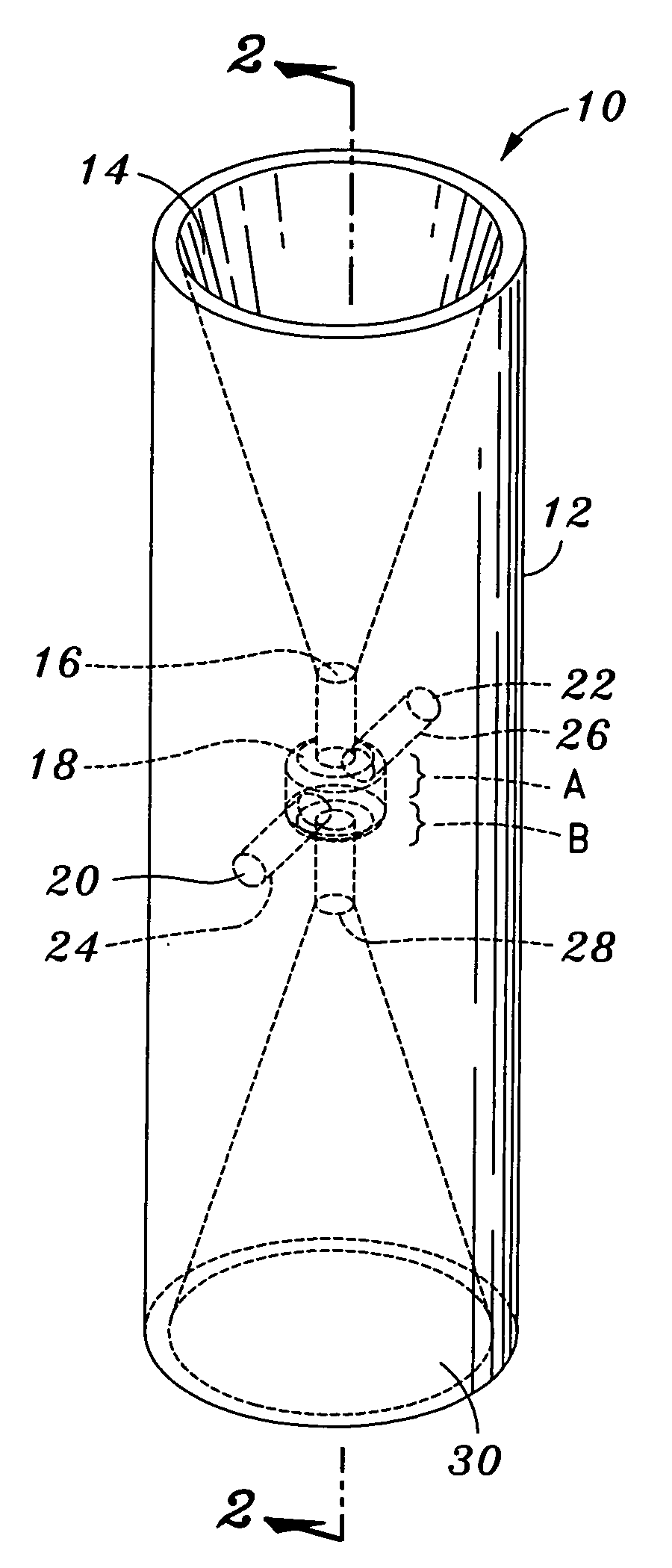
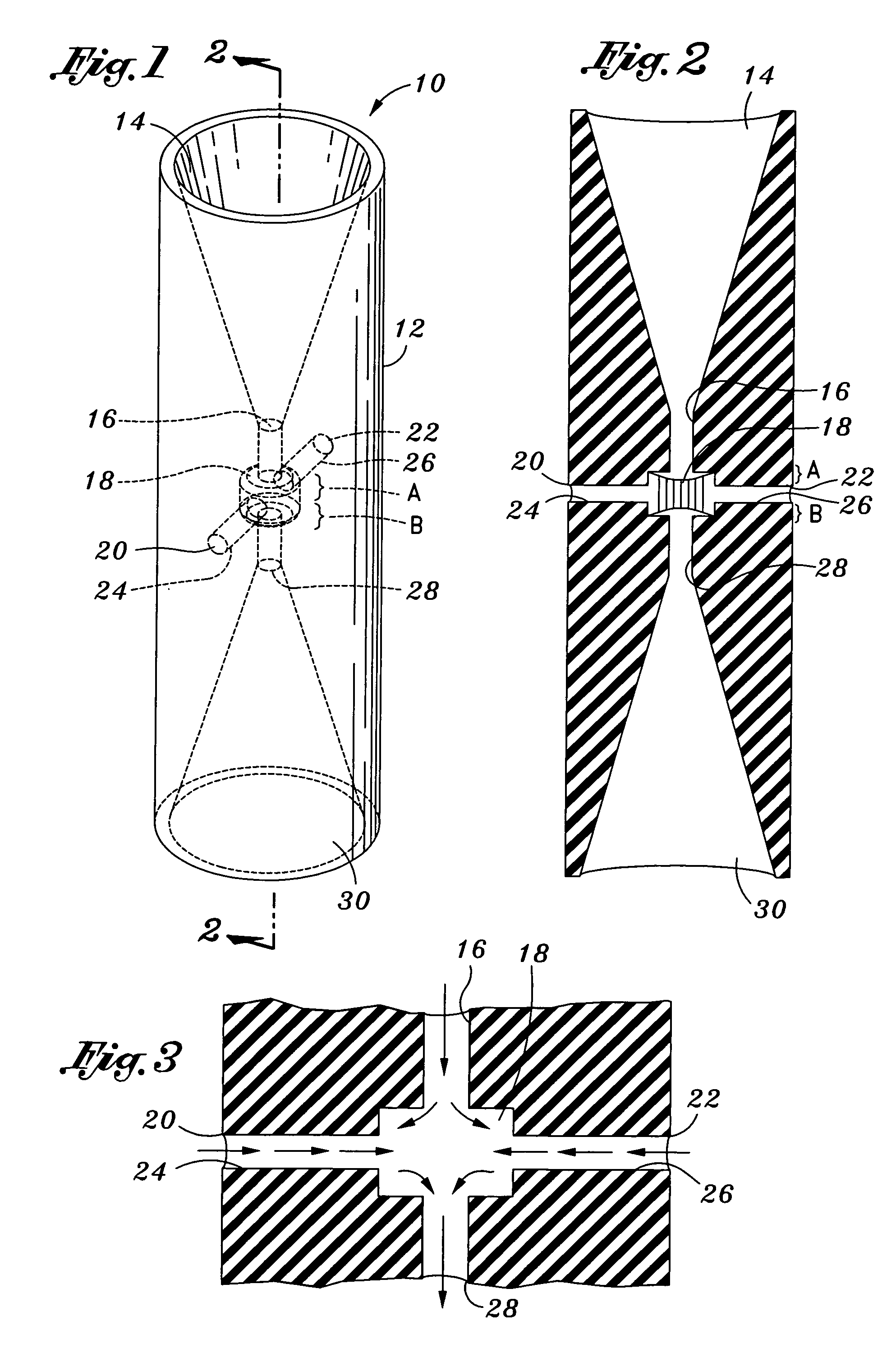
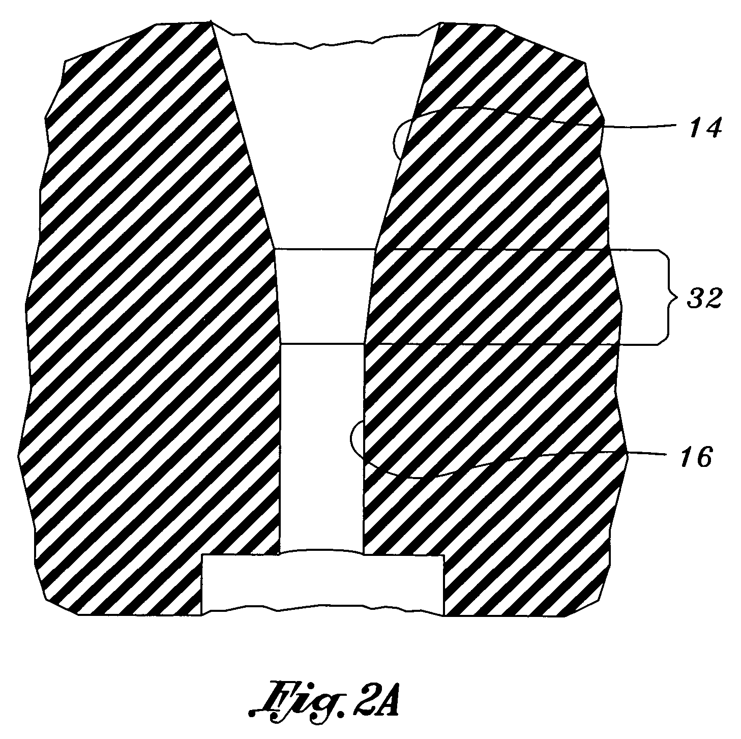
[0019]Referring now to the figures, and initially to FIG. 1, there is perspectively illustrated an improved venturi apparatus 10 that is operative to facilitate the assimilation and mixture of two or more fluids in a manner that is exceptionally more effective and efficient than prior art methods. At the outset, it should be understood that the term “fluid” as used herein can comprise any fluid-type substance and should be deem...


PUM

PropertyMeasurementUnit
diameteraaaaaaaaaa
diameteraaaaaaaaaa
heightaaaaaaaaaa

Abstract

An improved venturi apparatus for facilitating the mixture of fluid substances. The apparatus preferably has first funnel section operative to receive a fluid and channel the same through a first cylindrical section or passageway. The first cylindrical section is fluidly connected to an intermediate passageway having a diameter larger than the first cylindrical section. At least one sidearm passageway is fluidly connected to the intermediate passageway into which at least one second fluid is introduced. The at least one sidearm passageway is preferably configured to fluidly interconnect with the intermediate passageway at approximately the medial portion of the intermediate passageway. Fluidly connected to the intermediate passageway is a second cylindrical section that is operative to direct the flow of the intermixed fluids to a second exit funnel section. The improved venturi apparatus is exceptionally efficient at drawing in a second fluid and effective in facilitating the mixture of two or more gasses, liquids or combinations thereof.

Description

CROSS-REFERENCE TO RELATED APPLICATIONS[0001]Not ApplicableSTATEMENT RE: FEDERALLY SPONSORED RESEARCH / DEVELOPMENT[0002]Not ApplicableBACKGROUND[0003]The present invention is directed to an improved venturi device, and more particularly, an improved venturi device that is operative to facilitate the mixture of two or more fluids.[0004]Venturi-type devices are well-known in the art. Generally, such devices comprise fittings or tubular structures, and in particular pipe structures, that are constricted in the middle and flared on both ends. When a fluid, such as a gas or liquid, is passed through the venturi, the fluid's velocity of flow is caused to increase whereas the fluid's pressure is correspondingly caused to decrease. Such devices are used in a variety of applications, and especially in measuring fluid flow or for creating suction as for driving aircraft instruments or drawing fuel into the flow stream of a carburetor.[0005]Along these lines, venturi devices are frequently util...

Claims


Application Information

Patent Timeline
Patent Type & Authority Patents(United States)
IPC IPC(8): B01F3/04
CPCB01F5/0413B01F5/0428B01F3/0446Y10S261/75B01F2215/0072B01F25/31242B01F25/312B01F2101/17B01F23/2326B01F23/20B01F25/00B01F23/232
Inventor SABADICCI, RIONELSON, LARRY D.
Owner GREENFIELD WORLD TRADE
Learn More