Mobile robot charge station return system

a mobile robot and charge station technology, applied in the field of mobile robots, can solve the problems of time required for the return, the operation of the mobile robot may be stopped, and the inability to calculate the distance information to the charge station, etc., and achieve the effect of shortening the tim

Inactive Publication Date: 2009-11-10
LG ELECTRONICS INC
View PDF5 Cites 56 Cited by
  • Summary
  • Abstract
  • Description
  • Claims
  • Application Information

AI Technical Summary

Benefits of technology

[0012]Accordingly, it is an object of the present invention to provide a mobile robot charge station return system, which may effectively return a mobile robot to a charge station by calculating direction information and position information of a charge station from charge station position guidance signals.
[0014]The mobile robot charge station return system of the present invention transmits charge station position guidance signals to different areas in such a way that different emitting distances of the charge station position guidance signals change according to a predetermined time period. This causes an exact distance and direction between the charge station and the mobile robot to be calculated from the charge station position guidance signals that allows the mobile robot to be returned to the mobile robot within a shorter time.

Problems solved by technology

However, since such a method randomly moves the mobile robot along a wall surface, time required for returning to a chare station changes depending on areas in which the mobile robot is located.
Further, according to this method, when the artificial mark attached to the chare station is detected late, the operation of the mobile robot may be stopped due to the consumption of the battery thereof.
However, the conventional mobile robot can calculate only direction information of a charge station but cannot calculate distance information to the charge station from a signal emitted from the charge station.
Accordingly, it is difficult to modify a charge station return path until the mobile robot mechanically or electrically contacts with the charge station.

Method used


Image

  • Mobile robot charge station return system
  • Mobile robot charge station return system
  • Mobile robot charge station return system

Examples


Embodiment Construction

[0022]The present invention now will be described more fully hereinafter with reference to the accompanying drawings, in which embodiments of the invention are shown.

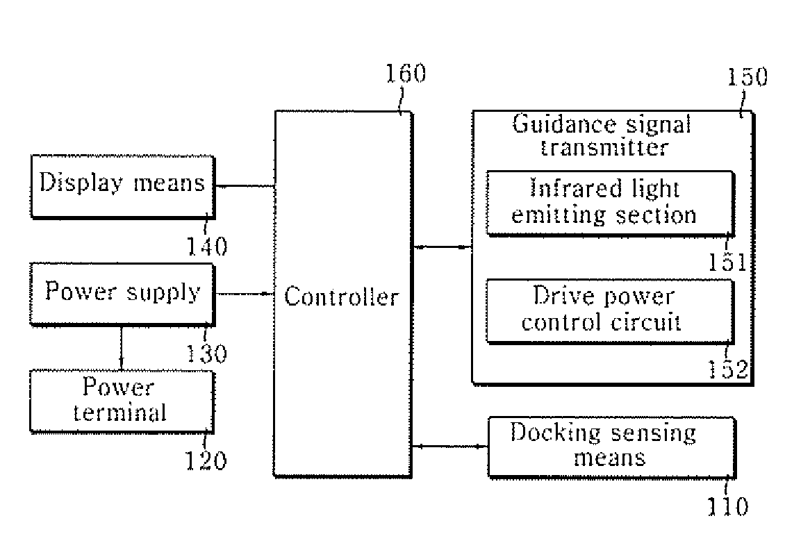
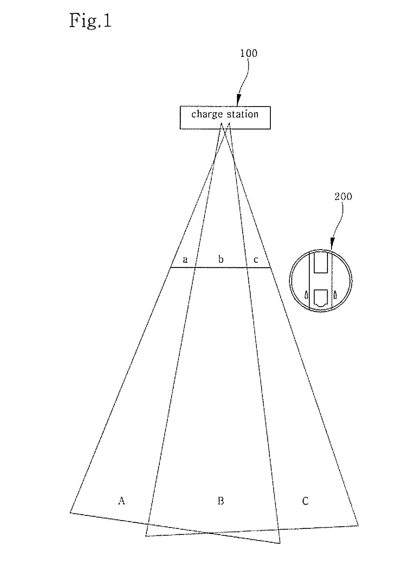
[0023]FIG. 1 is a view schematically showing a mobile robot charge station return system according to the present invention. As shown, the mobile robot charge station return system according to the present invention includes a charge station 100 and a mobile robot 200. The charge station 100 transmits charge station position guidance signals to different areas in such a way that different transmitting distances of the charge station position guidance signals change according to a predetermined time period. The mobile robot 200 receives charge station position guidance signal, calculates direct and distance information of the charge station, and returns to the charge station 100 according to the calculated direct and distance information of the charge station.

[0024]The charge station 100 supplies power necessary to drive...


PUM


Abstract

Disclosed is a mobile robot charge station return system, which may return a mobile robot to a charge station exactly and rapidly according to a charge station position guidance signal emitted from the charge station. The mobile robot charge station return system includes a charge station for transmitting charge station position guidance signals to different areas in such a way that different emitting distances of the charge station position guidance signals change according to a predetermined time period; and a mobile robot for receiving the charge station position guidance signals, calculating direction and distance information, and returning to the charge station according to the calculated direction and distance information.

Description

CROSS-REFERENCE TO RELATED APPLICATIONS[0001]This application claims benefit under 35 U.S.C. §119 from Korean Patent Application No. 2005-0101793, filed on Oct. 27, 2005, the entire content of which is incorporated herein by reference.BACKGROUND OF THE INVENTION[0002]1. Field of the Invention[0003]The present invention relates to a mobile robot, and more particularly, to a mobile robot charge station return system, which may return a mobile robot to a charge station exactly and rapidly according to a charge station position guidance signal emitted from the charge station.[0004]2. Description of the Related Art[0005]Robots have been developed for industrial purposes, which have been used for factory automatization, or for gathering or collecting information in a limited environment in which persons is unbearable, in stead of persons. Recently, such a robot-engineering field has been increasingly developed through the use in the most up-to-date space development industry, which result...

Claims


Application Information

Patent Timeline
Patent Type & Authority Patents(United States)
IPC IPC(8): B25J5/00
CPCG05D1/0225G05D1/0242G05D2201/0203
Inventor KIM, SANG-YUNKIM, YOUNG-GIE
Owner LG ELECTRONICS INC
Why Eureka
Try Eureka