
Recording disk drive having shroud

a technology of recording disk and shroud, which is applied in the direction of recording information storage, maintaining head carrier alignment, instruments, etc., can solve the problems of airflow turbulence, and achieve the effect of effectively utilizing airflow and suppressing the vibration of the recording disk

Inactive Publication Date: 2009-11-10
KK TOSHIBA
View PDF31 Cites 11 Cited by
  • Summary
  • Abstract
  • Description
  • Claims
  • Application Information

AI Technical Summary

Benefits of technology

[0006]It is accordingly an object of the present invention to provide a recording disk drive capable of reliably suppressing vibration of a recording disk and effectively utilizing airflow. It is accordingly another object of the present invention to provide a component, to be incorporated in the recording disk drive, greatly useful to realize the aforementioned recording disk drive.
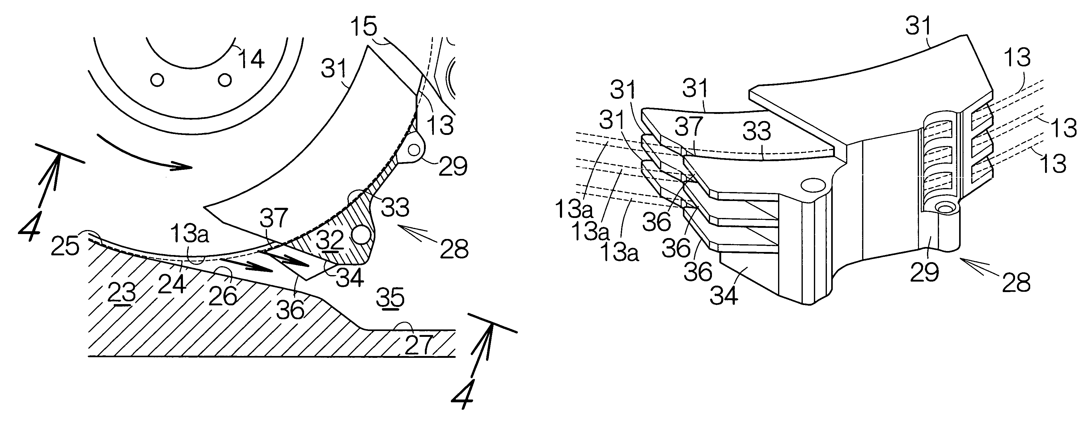
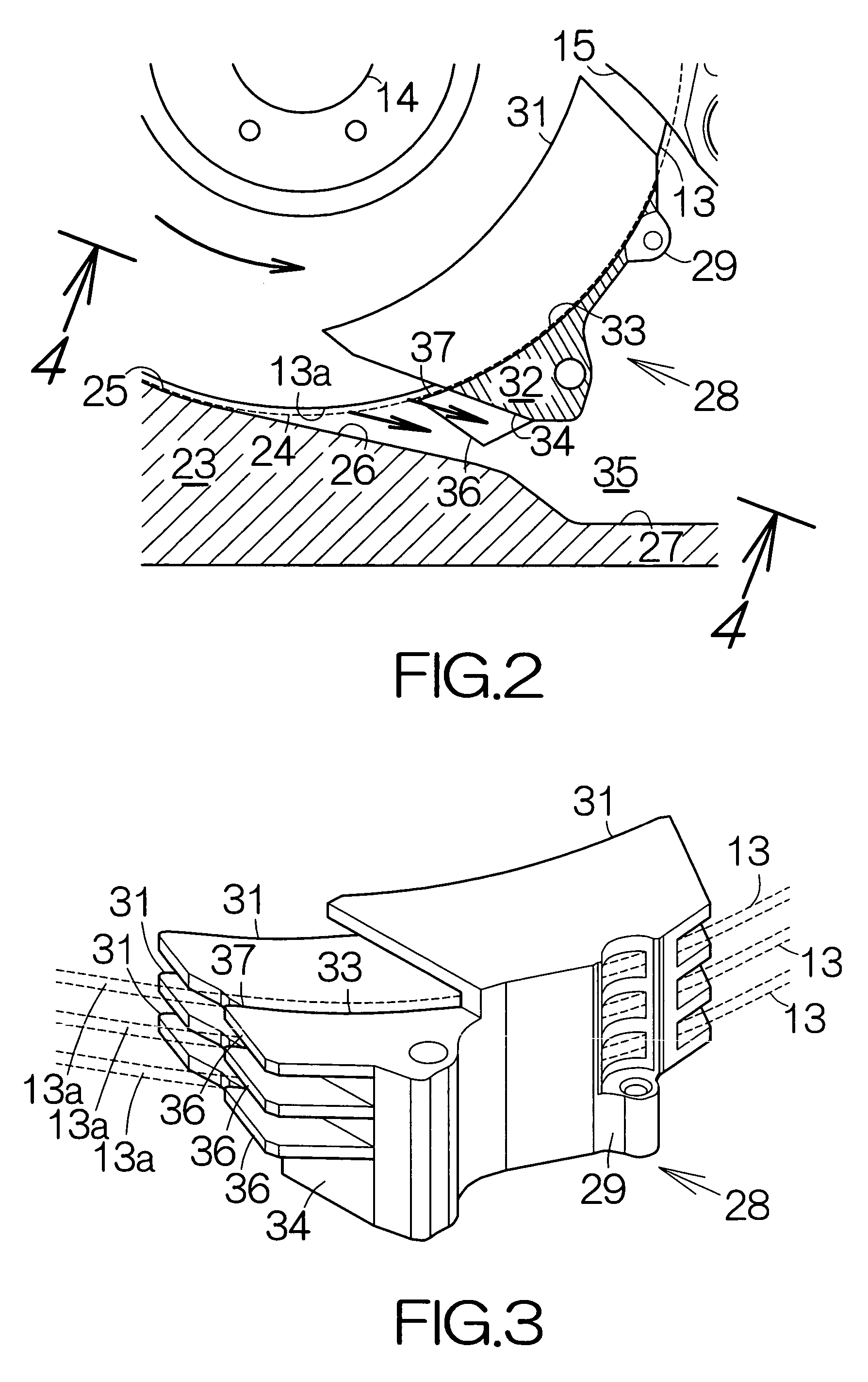
[0008]Airflow is generated along the rotating recording disk. The airflow is forced to flow toward the outer periphery of the recording disk during the rotation of the recording disk. The shroud plate faces the peripheral end surface of the recording disk at a certain constant distance at a position between the first and second shrouds. The shroud plate functions as a shroud. The shroud plate serves to suppress turbulence of the airflow. Vibration of the recording disk can thus be suppressed.
[0009]Moreover, the airflow generated along the rotational recording disk is allowed to flow into a space between the first and second shrouds. The shroud plate is designed to extend along a virtual plane perpendicular to the rotation axis of the recording disk between the first and second shrouds. The airflow can be prevented from staying between the first and second shrouds. Vibration of the recording disk can be suppressed between the first and second shroud. Additionally, the airflow can effectively be taken out. The airflow can effectively be utilized.
[0010]A rectifier plate may be fixed to the second shroud so as to face a front or / and back surface of the recording disk at a certain distance in this recording disk drive. The rectifier plate serves to further suppress turbulence of the airflow. The second shroud, the shroud plate and the rectifier plate may be formed as a one-piece component. Establishment of the one-piece component serves to improve efficiency of an assembling process of the recording disk drive.
[0011]A guiding wall may be connected to the first shroud. The guiding wall may get remoter from the peripheral end surface of the recording disk at locations further downstream from the first shroud in the direction of the rotation of the recording disk. Likewise, an auxiliary guiding wall may be connected to the second shroud. The auxiliary guiding wall is designed to face the guiding wall at a distance. The guiding wall and the auxiliary guiding wall serve to effectively introduce the airflow into a space between the first and second shrouds.
[0012]The guiding wall and the auxiliary guiding wall may define an entrance of an air passage extending toward a heating component. The airflow effectively induced along the guiding wall and the auxiliary guiding wall is allowed to flow into the air passage. A large amount of the airflow is allowed to flow toward the heating component. The airflow serves to suppress an increase in temperature of the heating component.

Problems solved by technology

The break of the shroud induces turbulence of the airflow.

Method used


Image

  • Recording disk drive having shroud
  • Recording disk drive having shroud
  • Recording disk drive having shroud

Examples


Embodiment Construction

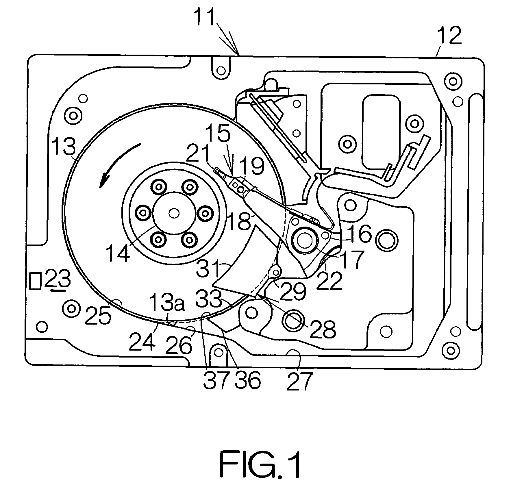
[0021]FIG. 1 schematically illustrates the inner structure of a hard disk drive (HDD) 11 as an example of a recording disk drive or storage device according to an embodiment of the present invention. The HDD 11 includes a box-shaped main enclosure 12 defining an inner space. At least one magnetic recording disk 13 is mounted on the driving shaft of a spindle motor 14 within the main enclosure 12. The spindle motor 14 is allowed to drive the magnetic recording disk 13 for rotation at a higher revolution speed such as 10,000 rpm, 15,000 rpm, or the like for example. A cover, not shown, is coupled to the main enclosure 12 so as to define the closed inner space between the main enclosure 12 and the cover itself.

[0022]A head actuator 15 is also accommodated in the inner space of the main enclosure 12. The head actuator 15 comprises an actuator block 16. The actuator block 16 is coupled to a vertical support shaft 17 for relative rotation. Rigid actuator arms 18 are defined in the actuato...


PUM

PropertyMeasurementUnit
frequencyaaaaaaaaaa
frequencyaaaaaaaaaa
constant distanceaaaaaaaaaa

Abstract

A first shroud and a second shroud are opposed to the peripheral end surface of a recording disk at a certain constant distance. The second shroud is spaced downstream from the first shroud in the direction of the rotation of the recording disk. A shroud plate is opposed to the peripheral end surface of the recording disk at a position between the first and second shrouds. The shroud plate functions as a shroud. The shroud plate serves to suppress turbulence of airflow. Vibration of the recording disk can be suppressed. Moreover, if the shroud plate is designed to extend along a virtual plane perpendicular to the rotation axis of the recording disk, the airflow is prevented from staying between the first and second shrouds. The airflow can effectively be taken out. The airflow can effectively be utilized.

Description

BACKGROUND OF THE INVENTION[0001]1. Field of the Invention[0002]The present invention relates to a recording disk drive such as a hard disk drive (HDD). In particular, the invention relates to a recording disk drive comprising: a recording disk; and a shroud designed to face the peripheral end surface of the recording disk at a certain distance.[0003]2. Description of the Prior Art[0004]A shroud is located at a location outside a magnetic recording disk in a hard disk drive (HDD), for example. A shroud surface is defined in the shroud so as to face the peripheral end surface of the magnetic recording disk at a certain distance. The shroud surface is defined along a predetermined cylindrical space. When the magnetic recording disk rotates, airflow is generated along the surface of the magnetic recording disk. The shroud surface serves to suppress turbulence of the airflow.[0005]The shroud breaks at a range of the swinging movement of a head actuator. The break of the shroud induces t...

Claims


Application Information

Patent Timeline
Patent Type & Authority Patents(United States)
IPC IPC(8): G11B33/14G11B5/60G11B25/04G11B21/22
CPCG11B5/6005G11B5/012G11B5/5582G11B5/59694
Inventor SUWA, MASAYAMATSUDA, YOSHIHARU
Owner KK TOSHIBA
Learn More