
Engine exhaust emission control device and exhaust emission control method

a technology for exhaust emission control and engine exhaust, which is applied in the direction of electrical control, exhaust treatment electric control, separation process, etc., can solve the problems of unnecessary consumption of urea water, insufficient ammonia with respect to nox, and discharge of unpurified nox into urea water, etc., to achieve the effect of suppressing the discharge of nox and ammonia

Active Publication Date: 2009-11-17
VOLVO LASTVAGNAR AB +1
View PDF7 Cites 18 Cited by
  • Summary
  • Abstract
  • Description
  • Claims
  • Application Information

AI Technical Summary

Benefits of technology

[0007]An object of the present invention is to suppress the discharge of NOx and ammonia into the atmosphere when an abnormality occurs in an engine part or an SCR device.
[0013]According to the present invention, when an abnormality occurs in an engine part, and the NOx emission amount of the engine changes, an amount of the reducing agent to be added by the addition device can be controlled to counterbalance the actual NOx emission amount. Therefore, discharge of NOx due to an insufficient supply of the reducing agent, and discharge of the reducing agent due to an excessive supply, can be prevented. Moreover, when an abnormality occurs in the addition device, and the device becomes unable to add an accurate amount of the reducing agent, the engine control factor can be manipulated to suppress NOx formation itself. Therefore discharge of NOx can be suppressed.

Problems solved by technology

However, in the above SCR device there are the following problems.
In this case, if the urea water injection quantity is maintained at the normal level irrespective of an increase in the NOx emission amount, then the ammonia becomes insufficient with respect to the NOx, and unpurified NOx is discharged into the atmosphere.
On the other hand, if the urea water injection quantity is maintained at the normal level irrespective of a decrease in the NOx emission amount, then not only will the urea water be consumed unnecessarily, but excessive ammonia will be generated and the surplus ammonia will be discharged into the atmosphere.
Furthermore, it is assumed that an abnormality has occurred in the SCR device, and the urea water injection quantity has changed, or the ammonia content amount in the urea water (that is, the urea concentration) has changed.
In this case, since the ammonia addition amount to the exhaust gas changes, the proportion of NOx and ammonia deviates from an optimal value, and the reduction reaction does not proceed well, so that the NOx removal rate will not meet requirements.
When ammonia is excessively added due to an abnormality in the SCR device, the surplus ammonia is discharged into the atmosphere.

Method used


Image

  • Engine exhaust emission control device and exhaust emission control method
  • Engine exhaust emission control device and exhaust emission control method
  • Engine exhaust emission control device and exhaust emission control method

Examples


Embodiment Construction

[0022]Hereunder, an embodiment of the present invention is described with reference to the drawings.

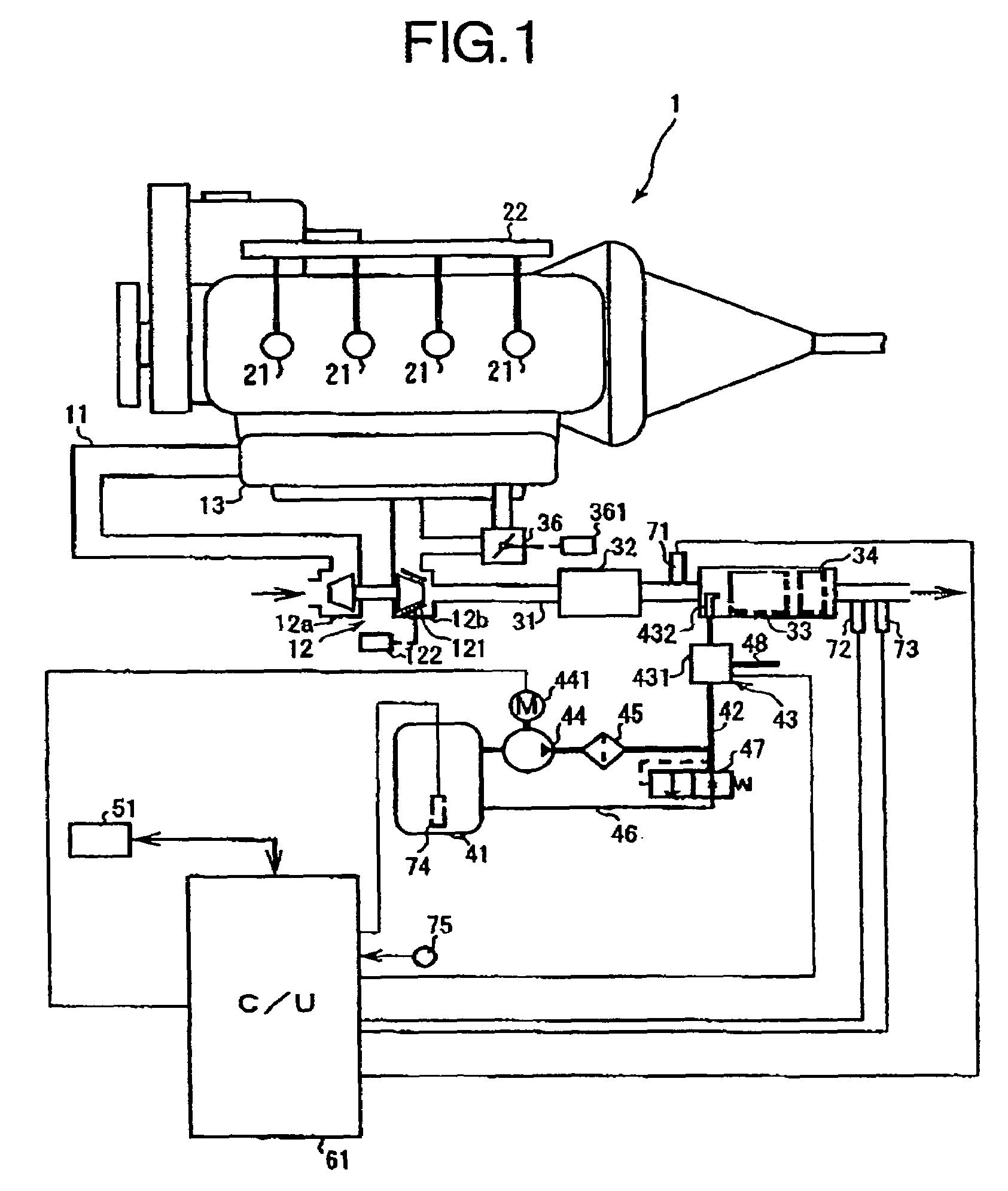
[0023]FIG. 1 shows a configuration of a motor vehicle engine (hereunder referred to as an “engine”) according to one embodiment of the present invention. In the present embodiment, a direct injection type diesel engine is used as an engine 1.

[0024]An air cleaner (not shown in the diagram) is fitted to an induction part of an intake air passage 11, and dust in the intake air is removed by the air cleaner. A compressor 12a of a variable nozzle type turbocharger 12 (which constitutes a “supercharger” in the present embodiment) is arranged in the intake air passage 11, and the intake air is compressed and discharged by the compressor 12a. The compressed intake air flows into a surge tank 13, and is distributed to respective cylinders in a manifold part.

[0025]In the engine main body, injectors 21 are installed on the cylinder head for each cylinder. The injectors 21 operate in accordance w...


PUM


Abstract

An engine C / U 51 detects an abnormality which has occurred in an engine, and outputs a signal that indicates the occurrence of this abnormality to an SCR-C / U 61. The SCR-C / U 61 increases and decreases the urea water injection quantity corresponding to the abnormality which has occurred. On the other hand, the SCR-CU 61 detects an abnormality that has occurred in the SCR device, and outputs a signal that indicates the occurrence of this abnormality to an engine C / U 51. The engine C / U 51 controls an engine part such as an EGR valve, to reduce the NOx emission amount.

Description

[0001]This application is a 35 U.S.C. 371 of PCT / JP2004 / 013306, filed on Sep. 13, 2004.BACKGROUND OF THE INVENTION[0002]1. Field of the Invention[0003]The present invention relates to an engine exhaust emission control device and exhaust emission control method, and in particular, to technology for purifying nitrogen oxides discharged from a vehicle engine, using ammonia as a reducing agent.[0004]2. Description of the Related Art[0005]As a device for purifying air pollutants discharged from an engine, in particular nitrogen oxides (referred to hereafter as “NOx”) in exhaust gas, using a secondary-treatment, the following SCR (Selective Catalytic Reduction) device is known. This SCR device is installed in an exhaust gas passage of an engine, and includes an injection nozzle that injects an aqueous solution of ammonia or a precursor thereof. The ammonia injected by this injection nozzle functions as a reducing agent, and reacts with NOx on a catalyst, to reduce and purify the NOx. Mor...

Claims


Application Information

Patent Timeline
Patent Type & Authority Patents(United States)
IPC IPC(8): F01N3/18B01D53/94F01N3/24F01N3/08F01N3/20F01N11/00F01N13/02F02B37/00F02D41/00F02D41/02F02D41/22
CPCF01N3/2066F01N3/208F01N11/00F01N13/009F02D41/22F01N2550/05F01N2610/02F02B37/00F02D41/0235Y02T10/40Y02T10/47Y02T10/24F02D41/0065Y02A50/20Y02T10/12
Inventor NISHINA, MITSUHIROKURITA, HIROYUKIKATOU, TOSHIKAZU
Owner VOLVO LASTVAGNAR AB
Learn More