A kind of exhaust gas under the ejection stage combustion w flame boiler

A staged combustion and flame technology, which is applied to the combustion of block fuel and gaseous fuel, the combustion of liquid fuel and gaseous fuel, the combustion of gaseous fuel and powder fuel, etc. It can solve the problem of high emission and reduce NOx Emissions, suppression of NOx formation, and reduction of excess air ratio

Inactive Publication Date: 2011-12-28
HARBIN INST OF TECH
View PDF4 Cites 12 Cited by
  • Summary
  • Abstract
  • Description
  • Claims
  • Application Information

AI Technical Summary

Problems solved by technology

[0005] The purpose of the present invention is to solve the problem of NO in operation of the W flame boiler of the single-stage injection staged combus

Method used


Image

  • A kind of exhaust gas under the ejection stage combustion w flame boiler
  • A kind of exhaust gas under the ejection stage combustion w flame boiler
  • A kind of exhaust gas under the ejection stage combustion w flame boiler

Examples


specific Embodiment approach 1

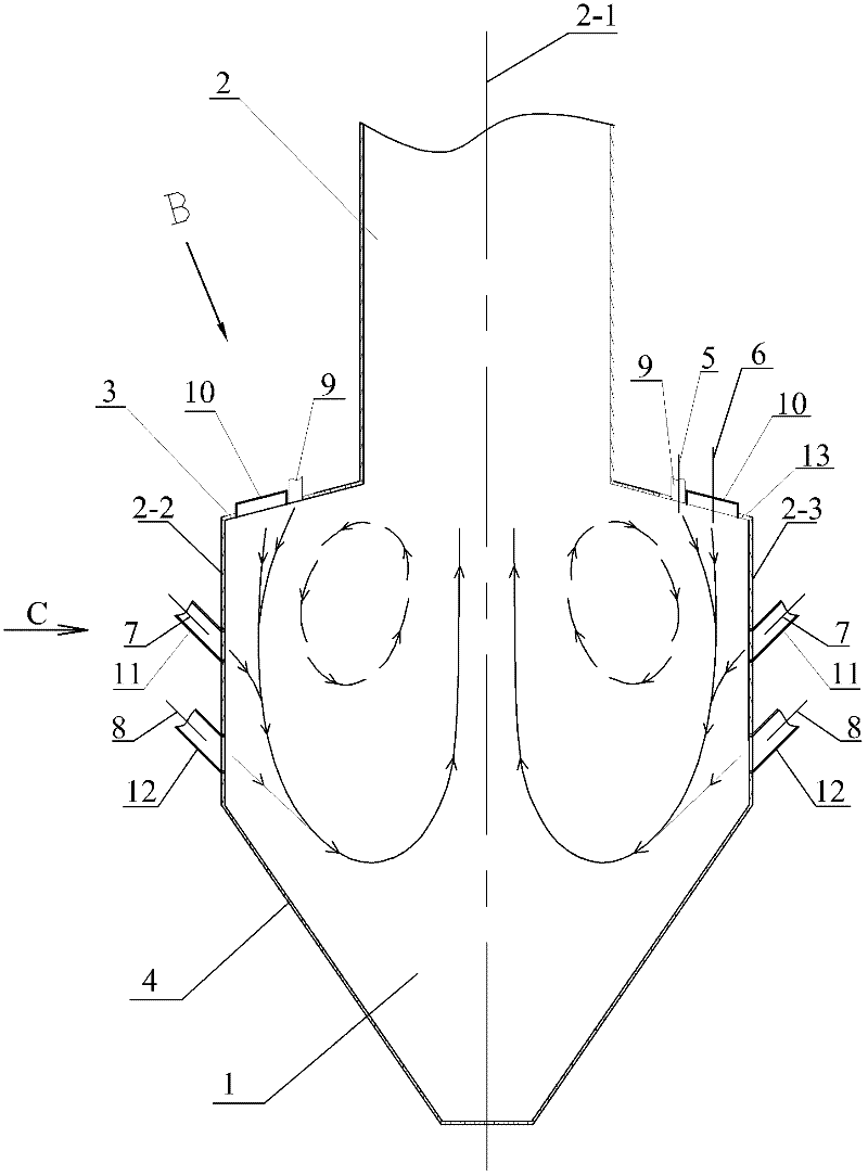
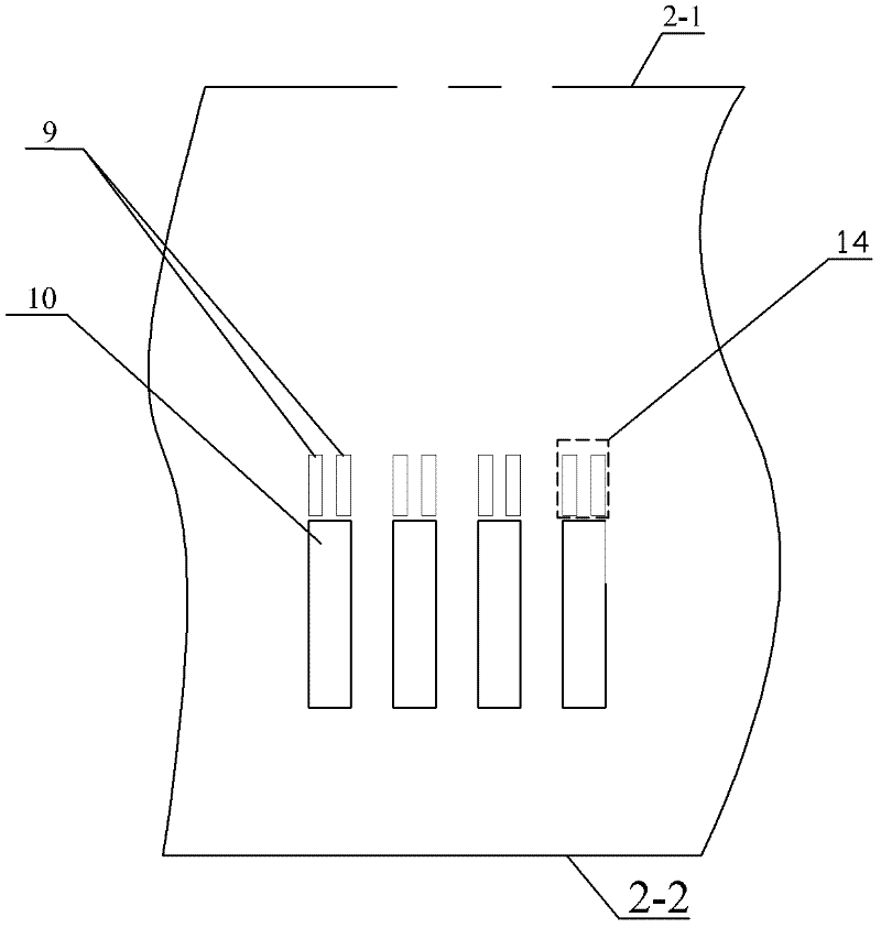
[0009] Embodiment 1: Combining Figure 1 to Figure 3 Illustrating this embodiment, this embodiment includes a furnace chamber composed of a lower furnace body 1 , an upper furnace body 2 , a front furnace arch 3 and a rear furnace arch 13 , a plurality of symmetrically arranged on the front furnace arch 3 and the rear furnace arch 13 . The rich pulverized coal airflow nozzle 9 and a plurality of secondary air nozzles 10 are on the front furnace arch 3 from the furnace center 2-1 to the front wall water wall 2-2 of the furnace and on the rear furnace arch 13 from the furnace center 2 Between -1 and the water-cooled walls 2-3 of the back wall of the furnace, a plurality of rich pulverized coal airflow nozzles 9 and a plurality of secondary air nozzles 10 are arranged in sequence. The airflow nozzles 9 are close to each other, and every two dense coal dust airflow nozzles 9 that are close together form a concentrated coal dust airflow nozzle group 14, and a plurality of concentra...

specific Embodiment approach 2

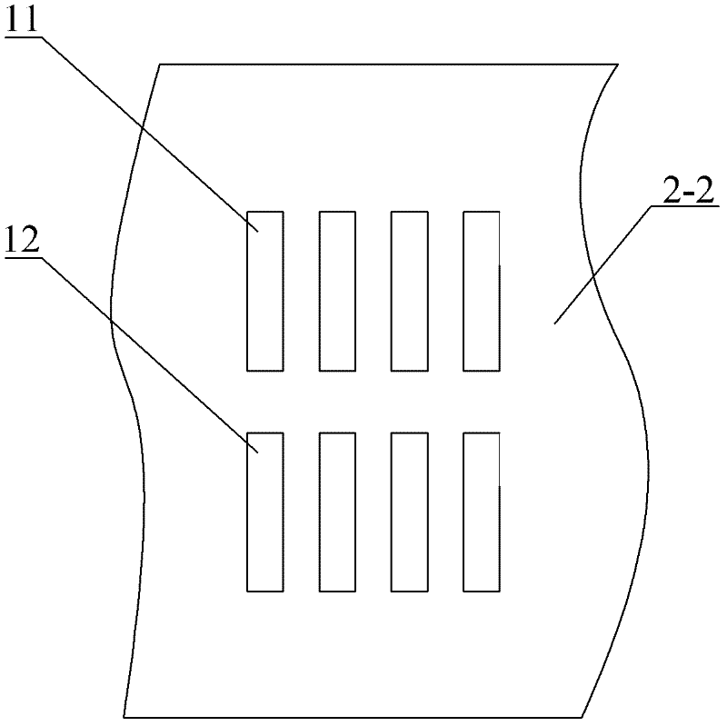
[0010] Specific implementation mode 2: Combining figure 1 This embodiment is described. The difference between this embodiment and the specific embodiment 1 is that it also adds a plurality of tertiary air nozzles 12, and the plurality of tertiary air nozzles 12 are divided into two groups. The arrangement of the two groups of tertiary air nozzles 12 is: in the lower furnace The lower parts of the front wall water-cooling wall 2-2 and the rear wall water-cooling wall 2-3 of the body 1 are respectively provided with a group of tertiary air nozzles 12 along the width direction thereof. The multiple tertiary air nozzles 12 are in one-to-one correspondence with each other, and the multiple pulverized coal airflow nozzles 11 on the water-cooled wall 2-3 of the rear wall are in one-to-one correspondence with the multiple tertiary air nozzles 12. The wind entering the furnace through the tertiary air nozzle 12 is the tertiary air 8, and its wind speed is the same as that of the seco...


PUM


Abstract

The utility model relates to a W-flame boiler with ejection and staged combustion under the exhaust gas, which relates to a W-flame combustion boiler. The invention solves the problem that the NOx emission is still relatively high during the operation of the W-flame boiler with the single-stage ejection staged combustion technology on the arch. The plurality of fresh pulverized coal airflow nozzles on the water-cooling wall of the front wall are symmetrically arranged with the plurality of fresh pulverized coal airflow nozzles on the water-cooling wall of the rear wall. The upper part is arranged in a straight line and at equal intervals along the width direction of the furnace. The multiple dense pulverized coal airflow nozzle groups on the front furnace arch correspond to the multiple thin coal powder airflow nozzles on the water wall of the front wall one by one. The multiple dense pulverized coal airflow nozzle groups are in one-to-one correspondence with the multiple fresh pulverized coal airflow nozzles on the water-cooled wall of the rear wall, and the angle between the centerline of each fresh pulverized coal airflow nozzle and the horizontal plane is 25°~45° . When the invention is used in W-flame boilers, the NOx emission can be greatly reduced and the combustible content of fly ash can be reduced.

Description

technical field [0001] The invention relates to a W flame combustion boiler, which belongs to the technical field of W flame boiler combustion. Background technique [0002] Inferior coals with low volatile content and low reactivity, such as anthracite and lean coal, often present the problems of difficult ignition, stable combustion and burning out during the combustion process. Developed countries in Europe and the United States developed arch combustion technology in the 1950s and 1960s, namely W flame combustion technology. Because the burner of the W flame combustion boiler is arranged on the furnace arch, the pulverized coal gas flow is shot down into the furnace from the arch, and the flame is turned up after a certain depth shot in the furnace, and the pulverized coal particles stay in the furnace for a longer time than conventional cutting The round and wall type combustion method is beneficial to obtain higher burnout; a large number of fire protection belts are ...

Claims


Application Information

Patent Timeline
IPC IPC(8): F23C5/08F23C7/00
Inventor 李争起况敏张岩陈智超
Owner HARBIN INST OF TECH
Why Eureka
Try Eureka