Variable valve timing and variable valve lift control system for automobile engine

An automotive engine and valve phasing technology, which is applied to engine components, machines/engines, mechanical equipment, etc., can solve the problem that the variable valve phase and the variable valve lift are not continuously changing, and achieve the goal of reducing NOX emissions. Effect

Inactive Publication Date: 2010-11-17
龚文资
View PDF6 Cites 2 Cited by
  • Summary
  • Abstract
  • Description
  • Claims
  • Application Information

AI Technical Summary

Problems solved by technology

However, the existing variable valve timing mechanism mainly changes the relative position of the crankshaft and the camshaft, increases the valve early opening angle and reduces the valve late closing angle, an

Method used


Image

  • Variable valve timing and variable valve lift control system for automobile engine
  • Variable valve timing and variable valve lift control system for automobile engine
  • Variable valve timing and variable valve lift control system for automobile engine

Examples


Example Embodiment

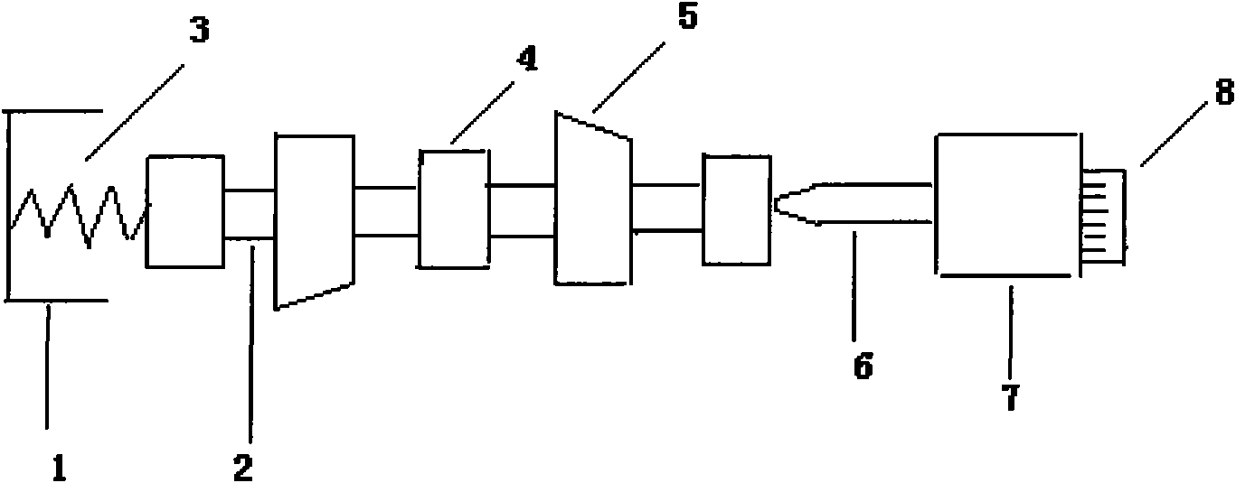
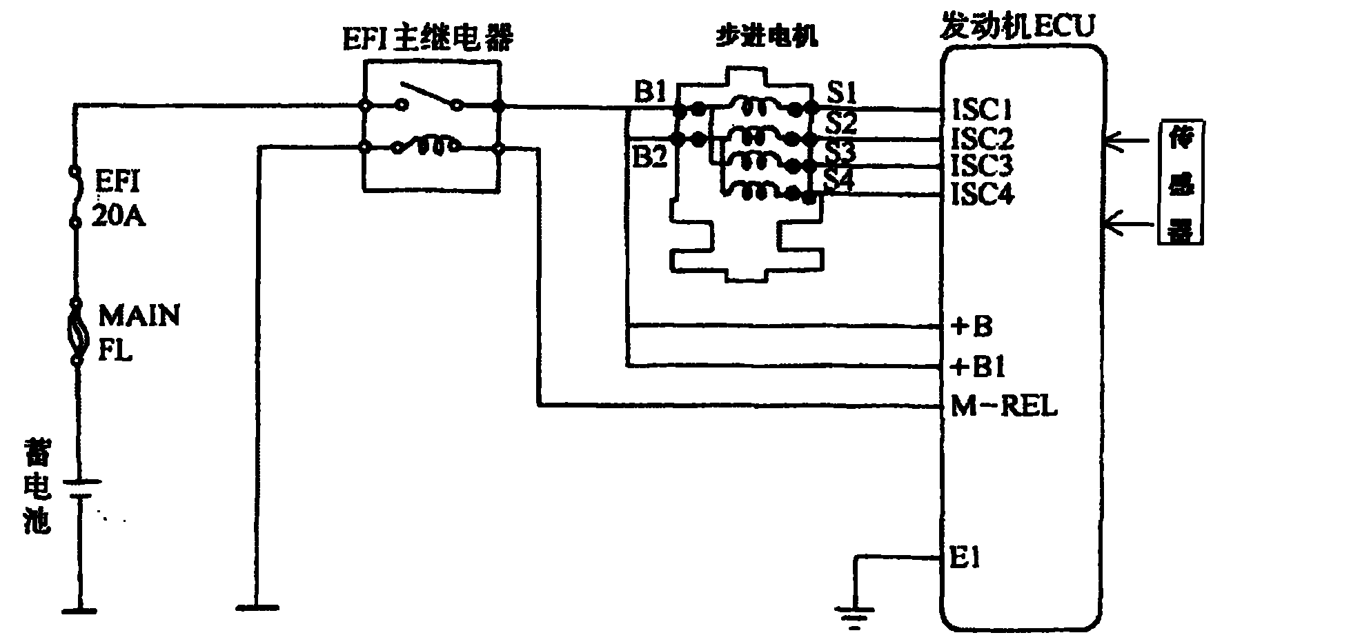
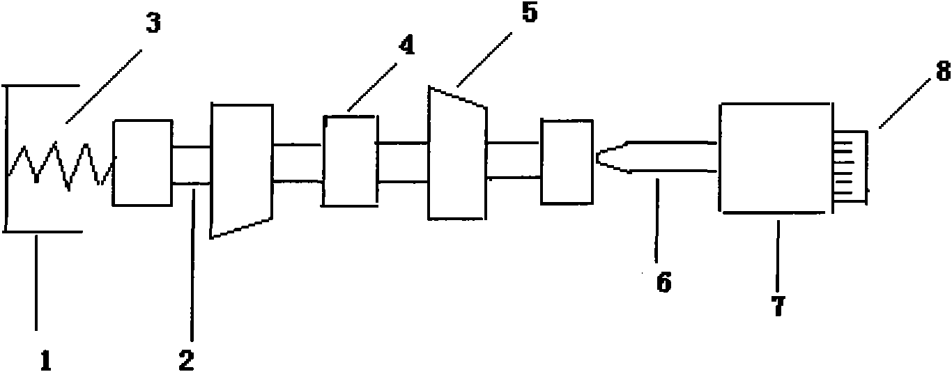
[0009] The principle of this control system is as follows figure 1 shown. The camshaft cam curve is a continuously changing curve of valve timing and valve lift that can meet the requirements of all engine working conditions. The axial position of the camshaft is driven by a stepping motor, which is controlled by the engine computer (ECU). Stepper motor control principle such as figure 2 shown. The engine computer mainly analyzes and calculates comprehensively based on signals such as speed, load, water temperature, and throttle opening. By controlling the grounding sequence and times of ISC1, ISC2, ISC3, and ISC4, the rotation direction and number of steps of the stepping motor can be controlled. And then precisely control the length of screw rod extension or shortening, the screw rod stretches out, pushes the cam shaft to move leftward, changes the contact position between the cam and the valve lifter, and also changes the valve timing and valve lift of the valve. When t...


PUM


Abstract

The invention discloses a variable valve timing and variable valve lift control system for an automobile engine, which comprises a return spring bracket 1, a cam shaft 2, a return spring 3, a shaft neck 4, a cam 5, a lead screw 6, a stepping motor 7 and a plug 8, wherein the return spring 3 is arranged in the return spring bracket 1; the return spring 3 is connected with the cam shaft 2; the shaft neck 4 is connected with the cam 5; the stepping motor 7 is connected with the cam 5 through the lead screw 6; and the plug 8 is arranged on the stepping motor 7 and is used for connecting an external power source. The system of the invention can be formed by direct expansion on an engine computer and does not need an individual control system. Moreover, by controlling an intake valve and an exhaust valve, exhaust gas recirculation (EGR) of an engine can be realized very conveniently, and emission of NOX is greatly reduced.

Description

technical field [0001] The invention relates to a variable valve timing and variable valve lift control system of an automobile engine. Background technique [0002] The valve timing and valve lift of an automobile engine have a great influence on engine performance. As the engine speed and load are different, the requirements for valve timing and valve lift are also different. As the engine speed and load increase, the valve opening angle, the valve closing angle and the valve lift should all increase, and vice versa. However, in the traditional engine valve train, the shape of the valve drive cam and the relative position between the camshaft and the crankshaft are fixed, and the valve timing and valve lift cannot be changed when the engine is running. can be optimized in any case. In order to solve the above problems, variable valve timing and variable valve lift devices for automobile engines have emerged as the times require. However, the existing variable valve tim...

Claims


Application Information

Patent Timeline
IPC IPC(8): F01L1/344F01L9/04F01L9/22
Inventor 龚文资
Owner 龚文资
Why Eureka
Try Eureka