
Diesel piston with sharp-step profile

a technology of stepped bowl and diesel piston, which is applied in the direction of pistons, machines/engines, combustion engines, etc., can solve the problems of contaminating oil, reducing affecting the efficiency of the combustion process, so as to improve the design of the stepped bowl, improve the mixing effect of combustion products, and reduce the effect of soot and nox emissions

Active Publication Date: 2019-06-13
GM GLOBAL TECH OPERATIONS LLC
View PDF14 Cites 2 Cited by
  • Summary
  • Abstract
  • Description
  • Claims
  • Application Information

AI Technical Summary

Benefits of technology

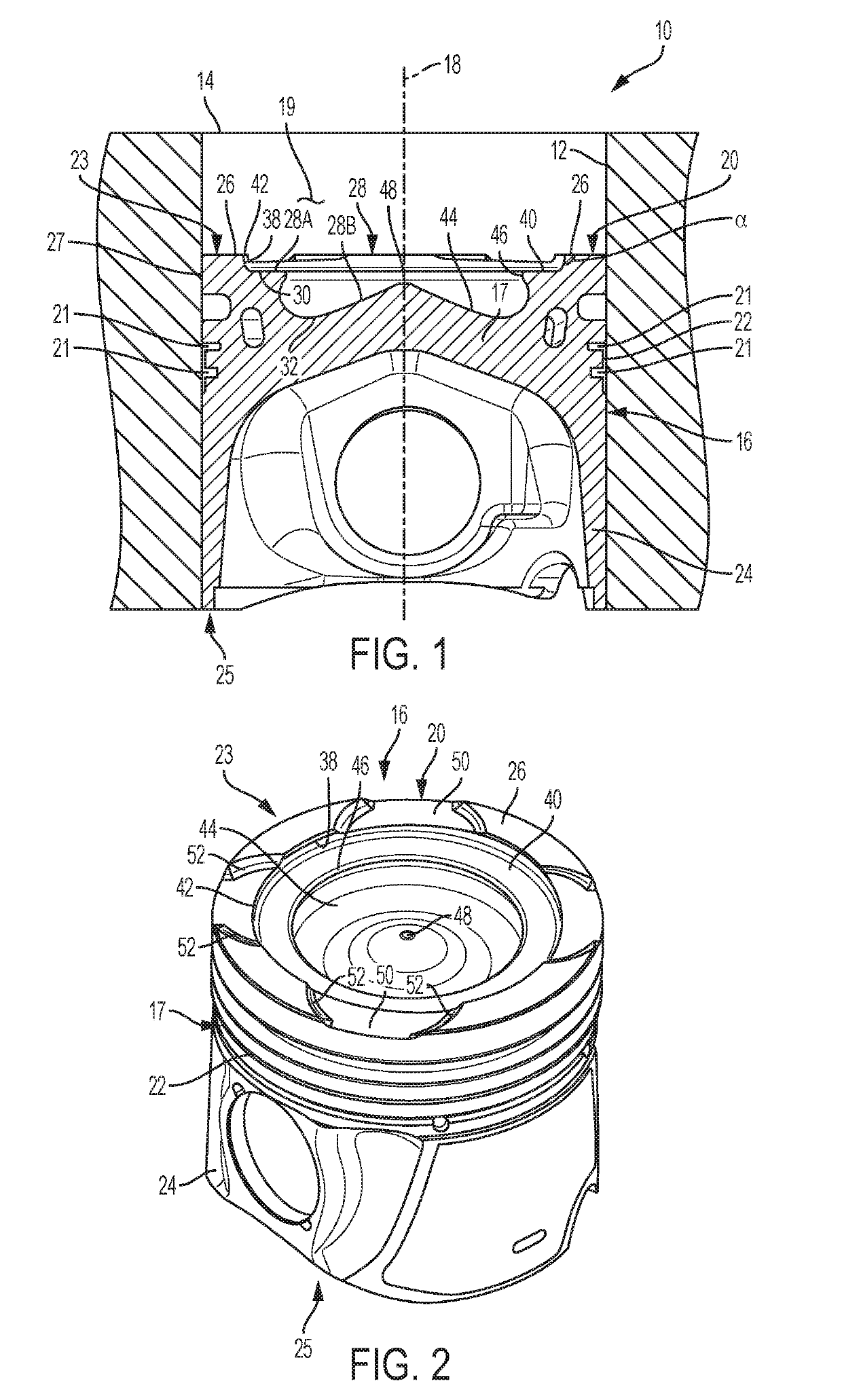
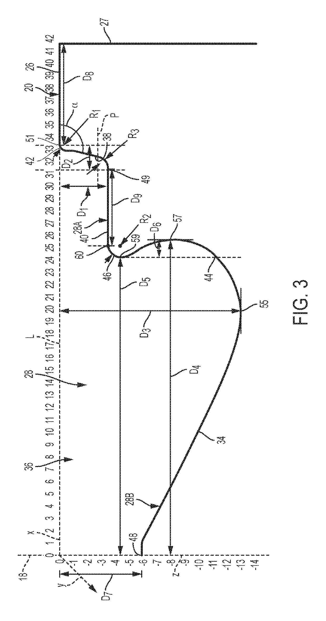
The present disclosure provides an improved design for the combustion bowl of a diesel engine. This design helps to mix combustion products with excess air in the cylinder, reducing soot and NOx emissions. The piston has a stepped bowl design with a bottom profile that has a smooth variation in curvature and a sharp step at the top. This design helps to generate powerful turbulent vortices, which enhance air fuel mixing, resulting in faster combustion, lower emissions, and very low levels of soot contamination in the engine oil. The lower bowl has a re-entrant, compact shape with smoothly varying curvature to improve mixing and minimize heat rejection at low loads. The upper bowl has flat and sharp-step surfaces to enhance air utilization and minimize liner-soot contact at high loads.

Problems solved by technology

Exhaust after treatment systems, however, can be costly.
In addition, soot resulting from combustion may be deposited on portions of the combustion chamber and may transfer to the engine oil system, thereby contaminating the oil.
Exhaust after-treatment systems do nothing to stop the transfer of soot into the engine oil, as it occurs upstream of the exhaust after-treatment system.

Method used


Image

  • Diesel piston with sharp-step profile
  • Diesel piston with sharp-step profile

Examples


Embodiment Construction

[0014]An example of the claimed piston will now be described more fully with reference to the accompanying drawings. Numerous specific details are set forth such as examples of specific components, devices, and methods, to provide a thorough understanding of embodiments of the present disclosure. It will be apparent to those skilled in the art that specific details need not be employed, that examples may be embodied in many different forms and that neither should be construed to limit the scope of the disclosure. In some examples, well-known processes, well-known device structures, and well-known technologies are not described in detail.

[0015]The terminology used herein is for the purpose of describing particular examples only and is not intended to be limiting. As used herein, the singular forms “a,”“an,” and “the” may be intended to include the plural forms as well, unless the context clearly indicates otherwise. The terms “comprises,”“comprising,”“including,” and “having,” are in...


PUM


Abstract

A piston for a diesel engine includes a piston body having a skirt and crown. The piston body has portions defining an outer combustion bowl and an inner combustion bowl within the piston body through the crown. The outer combustion bowl has a curved annular side wall extending from the crown surface and an annular flat shelf extending from the curved annular side wall. The new stepped bowl design integrates a bottom profile with smoothly varying curvature and a sharp step at the top. The annular flat shelf is recessed a distance in the range of 2.5-4.5 millimeters from a line coplanar with the crown surface. The piston body defines an outer convex curved surface connecting the curved annular side wall to the crown surface. The outer convex curved surface has a radius of curvature in the range of 0.25-0.75 millimeter.

Description

FIELD[0001]The present disclosure relates to a diesel piston having an outer combustion bowl and an inner combustion bowl for improved emissions, reduced fuel consumption, and higher power output.INTRODUCTION[0002]Diesel emissions are heavily regulated by federal governments. Accordingly, diesel systems designers have developed several improvements in diesel systems to reduce emissions. For example, enhanced air system designs provide higher rates of cooled EGR (exhaust gas recirculation), thereby reducing NOx emissions, and enhanced fuel injection systems reduce the inevitably higher soot emissions that would result from the use of higher EGR rates. Also, combined soot and NOx emissions after-treatment systems reduce emissions from diesel engines. Exhaust after treatment systems, however, can be costly.[0003]In addition, soot resulting from combustion may be deposited on portions of the combustion chamber and may transfer to the engine oil system, thereby contaminating the oil. Exh...

Claims


Application Information

Patent Timeline
Patent Type & Authority Applications(United States)
IPC IPC(8): F02F3/02F02B23/06
CPCF02F3/027F02B23/0687Y02T10/12
Inventor DIWAKAR, RAMACHANDRADOMENECH-LLOPIS, VICENTEPETERSON, RICHARD CVASSALLO, ALBERTO LORENZO
Owner GM GLOBAL TECH OPERATIONS LLC
Learn More