Wire clamping device

a wire clamping and wire technology, applied in the direction of soldering apparatus, manufacturing tools, capacitors, etc., can solve the problems of difficult to hold the wires in position, especially in the engine compartment or other restricted space, and achieve the effect of convenient use and easy manipulation

Active Publication Date: 2009-11-17
LISLE CORPORATION
View PDF7 Cites 11 Cited by
  • Summary
  • Abstract
  • Description
  • Claims
  • Application Information

AI Technical Summary

Benefits of technology

[0006]Briefly, the present invention comprises a wire clamping device for positioning first and second wire ends or wire leads relative to each other. The device includes a central body mount which has a base with a magnet. A support arm extends from the base. First and second laterally spaced magnetic platforms are incorporated on opposite sides of the support arm and are spaced from or positioned above the base portion. A first clamp arm with a magnet is cooperatively mounted on one of the platforms of the central body mount. A second clamp arm with a magnet is mounted on the other platform. Clamps or clips, such as alligator clips, are incorporated on each of the clamp arms. Each clamp arm is rotatable or movable about the surface of the associated platform so that each arm may be appropriately oriented to position a lead wire held in a clip mounted on the arm. Thus, each of the clamp arms is independently movable or rotatable and the base itself is positionable in a desired position on a magnetic surface, such as the inside of an engine compartment which is typically a steel surface. As a consequence, the wire clamp device of the invention may be fabricated in a very compact fashion, yet the device enables positioning of lead wires and gripping of lead wires in cramped spaces in a highly efficient manner so that the lead wires may be soldered together.
[0010]Another object of the invention is to provide a wire clamp device which is easily manipulated, rugged, inexpensive and easy to use.

Problems solved by technology

When repairing an automobile, holding the wires in position, particularly in the engine compartment or in some other restricted space is often a difficult task.

Method used


Image

  • Wire clamping device
  • Wire clamping device
  • Wire clamping device

Examples


Embodiment Construction

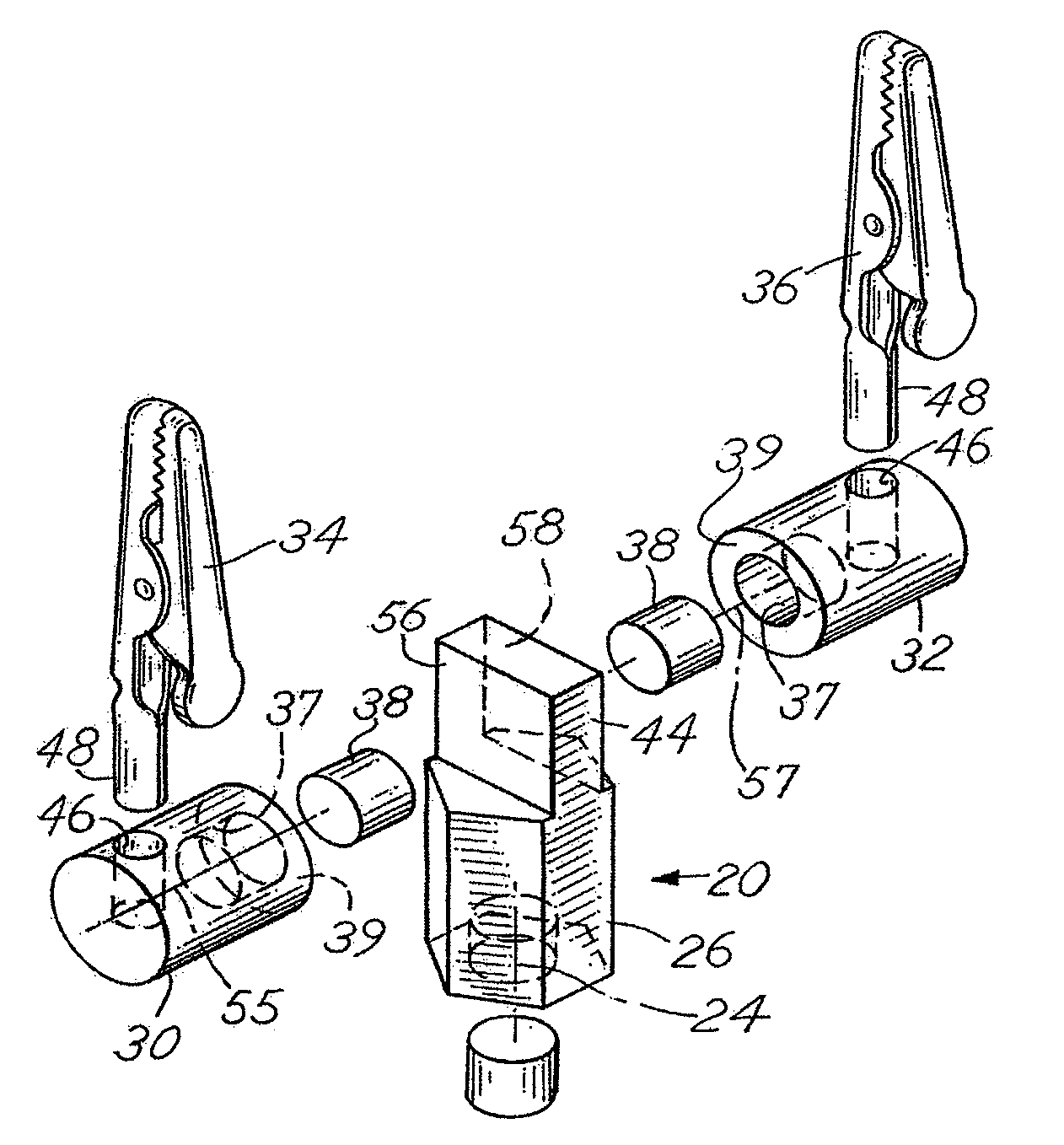
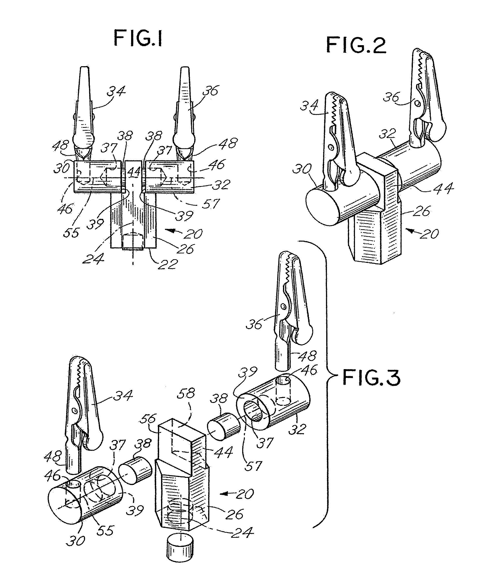
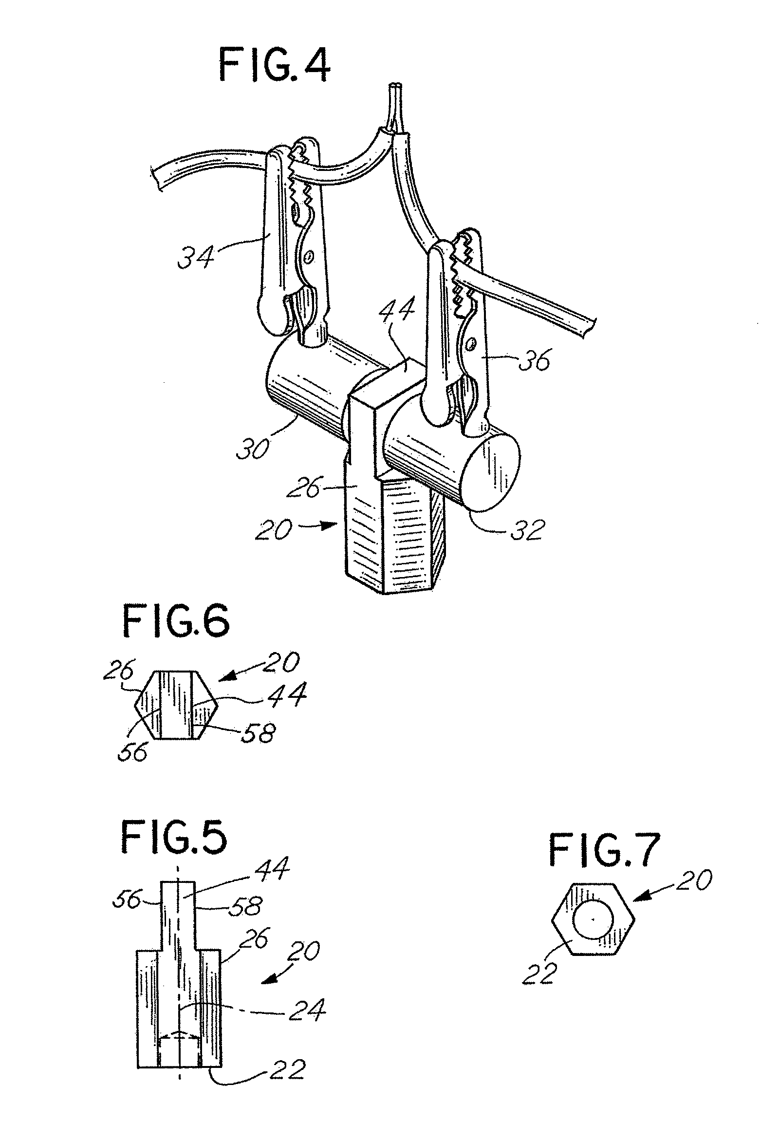
[0025]Referring to the figures, the wire clamp device of the invention comprises a body mount 20, having a bottom face or base surface 22 with a longitudinal axis 24 extending upwardly, and a support arm or post 26 extending upwardly from the base 22 in the axial direction. The wire clamp device further includes a left hand clamp arm assembly 30 and a right hand clamp arm assembly 32. A wire clamp or clip 34 is attached to the first or left hand clamp arm assembly 30. A wire clip arm or clamp 36 is attached to the second or right hand clip arm 32.

[0026]The clip arms or assemblies 30, 32 are substantially identical. Each clip arm 30 and 32 includes a recess 37 with a magnet 38 mounted therein. The magnet 38 extends beyond or projects from an inside edge 39 of each of the clip arms 30 and 32. The magnets 38 have a planar, exposed face. Each of the magnets 38 is retained within their respective openings 37 by means of an epoxy by way of example. The magnets 38 that are preferred in the...


PUM


Abstract

A wire clamp holder includes a magnetized central post or support body mount having left hand and right hand clamp arms or clip holders magnetically attached thereto and rotatable with respect thereto to permit maximum adjustability for positioning of lead wires held by wire clamping jaws associated with the clamp arms.

Description

BACKGROUND OF THE INVENTION[0001]In a principal aspect the present invention relates to a wire clamping device and, more particularly, to a device to engage the lead ends of separate wires and hold them in a position for joining or soldering the ends together.[0002]Often in automobile repair as well as repair of other wired products it is appropriate and necessary to connect wires by a soldering operation or alternatively to otherwise join the wires together. When repairing an automobile, holding the wires in position, particularly in the engine compartment or in some other restricted space is often a difficult task. This is particularly so when one is attempting to solder the wire ends together. Thus, there has developed the need to provide some type of mechanism to enable the leads of wires that are to be soldered to be joined or held relative to one another in a position that will facilitate soldering.[0003]There are numerous devices available which comprise clamping systems for ...

Claims


Application Information

Patent Timeline
Patent Type & Authority Patents(United States)
IPC IPC(8): B25B11/00
CPCB23K3/087B23K2201/38B23K2201/32B23K2101/32B23K2101/38
Inventor HALEY, RONALD JOSEPH
Owner LISLE CORPORATION
Why Eureka
Try Eureka